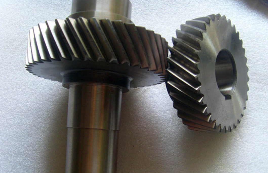
Helical gears exhibit superior load-bearing capacity and smoother transmission compared to spur gears, making them critical components in high-power precision transmission systems. Their widespread use in high-speed and heavy-load applications, such as wind turbines and marine propulsion, necessitates thorough analysis of thermal effects to prevent scuffing failures. This study investigates the contact characteristics, friction-induced heat generation, and steady-state temperature distribution of helical gears under varying operating conditions.

1. Contact Mechanics of Helical Gears
The meshing behavior of helical gears features time-varying contact line lengths due to their helical tooth geometry. The instantaneous contact line length can be expressed as:
$$L(t) = \begin{cases}
\frac{b}{\cos\beta_b} – \frac{(t/T_m – \varepsilon_\beta)p_{bt}}{\sin\beta_b} & 0 \leq t \leq T_m\varepsilon_\beta \\
\frac{b}{\cos\beta_b} & T_m\varepsilon_\beta < t \leq T_m\varepsilon_\alpha \\
\frac{(t/T_m – \varepsilon_\gamma)p_{bt}}{\sin\beta_b} & T_m\varepsilon_\alpha < t \leq T_m\varepsilon_\gamma
\end{cases}$$
Where parameters are defined in Table 1:
| Parameter | Description |
|---|---|
| $b$ | Face width |
| $\beta_b$ | Base helix angle |
| $p_{bt}$ | Base pitch |
| $\varepsilon_\alpha, \varepsilon_\beta$ | Transverse and overlap contact ratios |
2. Hertzian Contact Stress Analysis
The contact stress distribution in helical gears follows Hertzian contact theory. The maximum contact pressure and semi-contact width are calculated as:
$$ \sigma_{\text{max}} = \frac{4}{\pi} \sqrt{\frac{F_n E^*}{\pi L \rho^*}} $$
$$ a = \sqrt{\frac{4 F_n \rho^*}{\pi L E^*}} $$
Where equivalent parameters are:
$$ \frac{1}{\rho^*} = \frac{1}{\rho_1} + \frac{1}{\rho_2} $$
$$ \frac{1}{E^*} = \frac{1-\nu_1^2}{E_1} + \frac{1-\nu_2^2}{E_2} $$
| Parameter | Value (Active Gear) | Value (Driven Gear) |
|---|---|---|
| Number of teeth | 17 | 26 |
| Helix angle | 15° | 15° |
| Normal module | 4.5 mm | 4.5 mm |
| Face width | 20 mm | 20 mm |
3. Thermal Load Analysis
The frictional heat generation in helical gear meshing is governed by:
$$ q = \sigma_{\text{max}} \cdot f \cdot v_s \cdot \gamma $$
Where sliding velocity $v_s$ varies along the contact line:
$$ v_s = \omega_1 r_{b1} \sin\alpha_t – \omega_2 r_{b2} \sin\alpha_t $$
Heat partition between mating gears follows:
$$ q_1 = \frac{2a q \beta}{v_{1n}} $$
$$ \beta = \frac{\sqrt{\lambda_2 \rho_2 c_2}}{\sqrt{\lambda_1 \rho_1 c_1} + \sqrt{\lambda_2 \rho_2 c_2}} $$
4. Convection Heat Transfer
Convection coefficients for different gear surfaces:
| Surface | Convection Coefficient Formula |
|---|---|
| Tooth flank | $h_{mn} = \frac{0.228\lambda \mathrm{Re}^{2/3} \mathrm{Pr}^{1/3}}{d_p}$ |
| End face | $h_{de} = \frac{0.6\mathrm{Pr}\lambda}{(0.56 + 0.26\mathrm{Pr}^{1/2} + \mathrm{Pr})^{2/3}} \left(\frac{\omega}{\nu_r}\right)^{1/2}$ |
| Tooth tip/root | $h_{tf} = 0.664\lambda \mathrm{Pr}^{1/3} \left(\frac{\omega}{\nu_r}\right)^{1/2}$ |
5. Thermal Analysis Results
Steady-state temperature distributions under different torque conditions:
| Torque (Nm) | Maximum Temperature (°C) | High-Temperature Zone |
|---|---|---|
| 160 | 82.3 | Root region |
| 260 | 103.7 | Root and tip |
| 360 | 126.5 | Full tooth profile |
The parametric study reveals that:
$$ \Delta T \propto T^{0.68} \cdot n^{0.52} $$
Where $T$ is input torque and $n$ is rotational speed, demonstrating the strong thermal sensitivity of helical gears to operational parameters.
6. Conclusion
This comprehensive analysis of helical gear thermal-mechanical behavior provides critical insights for preventing scuffing failures. The developed numerical model enables accurate prediction of contact stresses and temperature distributions, particularly important for high-power transmission systems employing helical gears. Future work should incorporate thermo-elastic deformation effects for enhanced prediction accuracy.
