
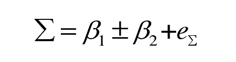
During gear hobbing, the hob axis and gear axis must meet a certain axis intersection angle. The installation axis intersection angle of gear hob refers to the minimum staggered angle between hob axis and gear axis, and the axis intersection angle is recorded as Σ:
Where:
β 1 – helix angle of indexing circle of gear hob (RAD);
β 2 – helix angle of gear indexing circle (RAD);
E Σ – installation error of axis intersection angle Σ.
The selection of the sign in the formula is related to the spiral angle direction of the gear hob and the workpiece. When machining helical cylindrical gear with gear hob, when the spiral direction of hob and helical gear is consistent, take “-” sign; On the contrary, take “+” sign.
When the hob and gear mesh at node C, the center distance between the hob and the workpiece is marked as a:
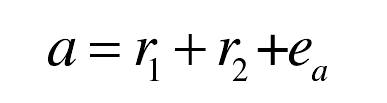
Where:
R1 — dividing circle radius of gear hob (mm);
R2 — radius of gear indexing circle (mm);
e α —— Center distance α Installation error.
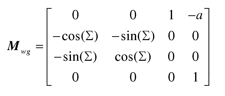
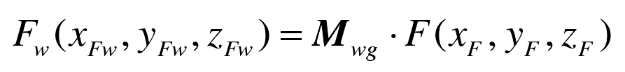
In gear hobbing, in order to facilitate the study of the meshing process between hob and gear, it is necessary to use coordinate transformation matrix to transform hob and gear into the same coordinate system. According to the definition of hob and gear coordinate system, coordinate transformation from gear coordinate system: SG, (OG: XG, YG, ZG) to hob coordinate system: SW (ow: XW, YW, ZW).
The matrix is marked as MWG:
Then, the coordinates FW (xfw, yfw, ZFW) of any point F (XF, YF, ZF) on the gear tooth surface in the gear hob coordinate system SW can be expressed as:
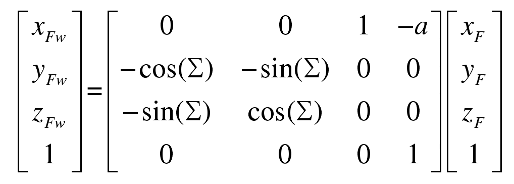
That is:
The gear tooth surface FW (xfw, yfw, ZFW) after coordinate transformation is combined with the hob, which is the three-dimensional meshing model in gear hobbing.