Without considering the installation error Σ e of the shaft intersection angle Σ, the helix angle of spur gear β 2 = 0, the intersection angle between gear hob axis and spur gear axis Σ is obtained from the formula:

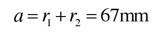
The installation center distance is not considered α Installation error e α 。 From the formula, the center distance:
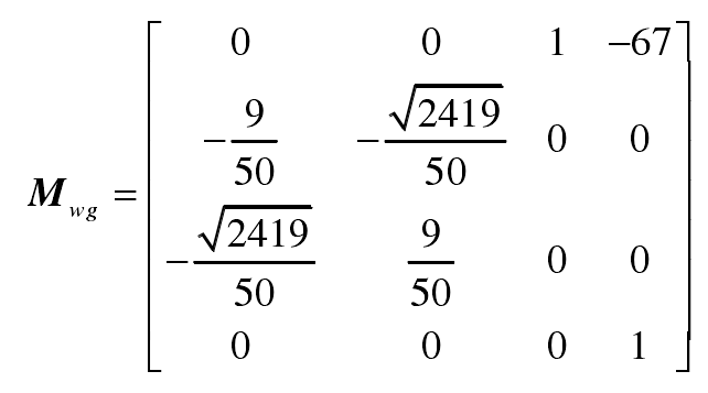
Axis intersection angle Σ and center distance α After calculation, the coordinate transformation matrix MWG can be obtained from the formula:
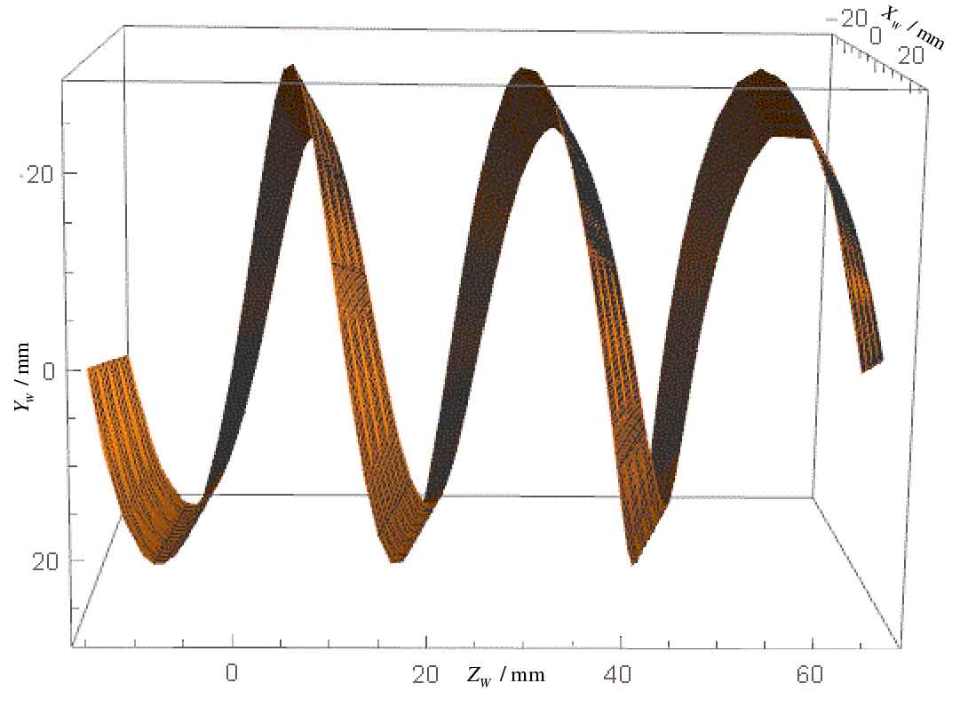
From the formula and matrix multiplication, the spatial coordinates FW (xfw, yfw, ZFW) of any point on the tooth surface of spur cylindrical gear in gear hob coordinate system SW (ow: XW, YW, ZW) can be obtained.
Based on Mathematica software, use parametricplot3d to draw three-dimensional parameter diagram command to simulate the right tooth surface of gear teeth in gear hob coordinate system SW (ow: XW, YW, ZW):

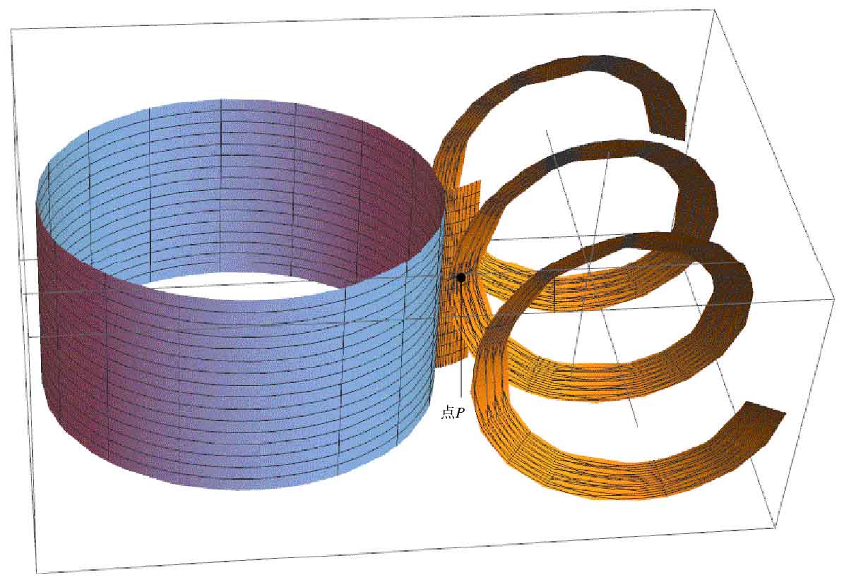
Through the show […] graphic combination display command, the gear tooth surface FW (xfw, yfw, ZFW) after coordinate transformation is superimposed with the three-dimensional model of gear hob in Figure 1 to obtain the three-dimensional simulation model of gear hob and spur cylindrical gear meshing, as shown in Figure 2, The involute helical surface of gear hob and the tooth surface of spur gear mesh at node P.