
Abstract: This article focuses on the research of high-modification cylindrical spur gears. It elaborates on the gear transmission calculation, three-dimensional modeling using UG (CAD), theoretical stress calculation based on Hertz theory, and finite element analysis with Ansys Workbench. The results show that the theoretical and simulation stress values are close, validating the effectiveness of the modeling and analysis methods. This research provides valuable references for the design and optimization of high-modification cylindrical spur gears.
1. Introduction
1.1 Gear Transmission Significance
Gear transmission is a crucial form of power transmission in modern machinery. It consists of driving and driven gears that transfer motion and torque through meshing. Spur gears, with their simple structure and reliable operation, are widely used. The performance and lifespan of gear transmissions directly impact the overall performance of mechanical equipment. Therefore, in-depth research on spur gears is of great significance for improving mechanical transmission efficiency and reliability.
1.2 Research Background and Objectives
Previous studies have explored various aspects of gear design and analysis. For example, some researchers have focused on contact and finite element analysis theories, using software like UG NX and SolidWorks for modeling and simulation. Others have investigated the influence of different modeling methods and parameters on gear performance. However, there is still a need for more comprehensive and in-depth research on high-modification cylindrical spur gears. This study aims to conduct detailed geometric calculations for high-modification cylindrical spur gears, perform three-dimensional parameterized modeling using UG (CAD), calculate theoretical stress values based on Hertz theory, and conduct transient finite element analysis with Ansys Workbench. By comparing the theoretical and simulation results, the study intends to provide a scientific basis and technical support for the design and optimization of high-modification cylindrical spur gears.
2. High-Modification Cylindrical Spur Gear Transmission Calculation
2.1 Gear Parameter Determination
Taking a pair of meshing small and large gears as an example, the known parameters are as follows (see Table 2):
| Name | Geometric Formula | Small Gear | Large Gear |
|---|---|---|---|
| Module (m) | – | 2.5 | 2.5 |
| Number of Teeth (z) | – | 30 | 65 |
| Pressure Angle (α) | – | 20° | 20° |
| Modification Coefficient (x) | – | 0.35 | -0.35 |
| Addendum Coefficient (h*α) | – | 1 | 1 |
2.2 Calculation Results and Analysis
Based on the above parameters, the following geometric dimensions of the gears can be calculated (see Table 3):
| Name | Geometric Formula | Small Gear | Large Gear |
|---|---|---|---|
| Pitch Diameter (d) | d=mz | 75 | 162.5 |
| Addendum Diameter (dα) | dα=d+2m(h*α+x) | 81.75 | 165.75 |
| Dedendum Diameter (df) | df=d-m(h*α-x-c) (where c=0.25m for m>1) | 70.5 | 154.5 |
| Addendum Height (hα) | hα=m(h*α+x) | 3.375 | 1.625 |
| Dedendum Height (hf) | hf=m(h*α-x+c) | 2.25 | 4 |
| Tooth Height (h) | h=hα+hf | 5.625 | 5.625 |
| Base Circle Radius (γb) | γb=mzcosα/2 | 35.2834 | 76.3500 |
| Base Pitch (Pb) | Pb=mπcosα | 7.38033 | 7.38033 |
| Circular Pitch (P) | P=mπ | 7.85394 | 7.85394 |
| Radial Clearance (c) | c=0.25m | 0.625 | 0.625 |
| Center Distance (α) | α=m(z1+z2)/2 | 118.75 | 118.75 |
These calculated geometric parameters provide the basis for subsequent three-dimensional modeling and stress analysis of the gears.
3. Three-Dimensional Modeling Based on UG (CAD)
3.1 UG (CAD) Software Introduction
UG is a powerful software integrating CAD/CAM/CAE. It offers a comprehensive modeling process, including explicit solid, surface modeling, and parametric direct modeling. With its high innovation, good quality, high efficiency, and complete functions, UG (CAD) is one of the most widely used 3D modeling software. It has unique advantages in complex product development and design.
3.2 Modeling Process of Small and Large Gears
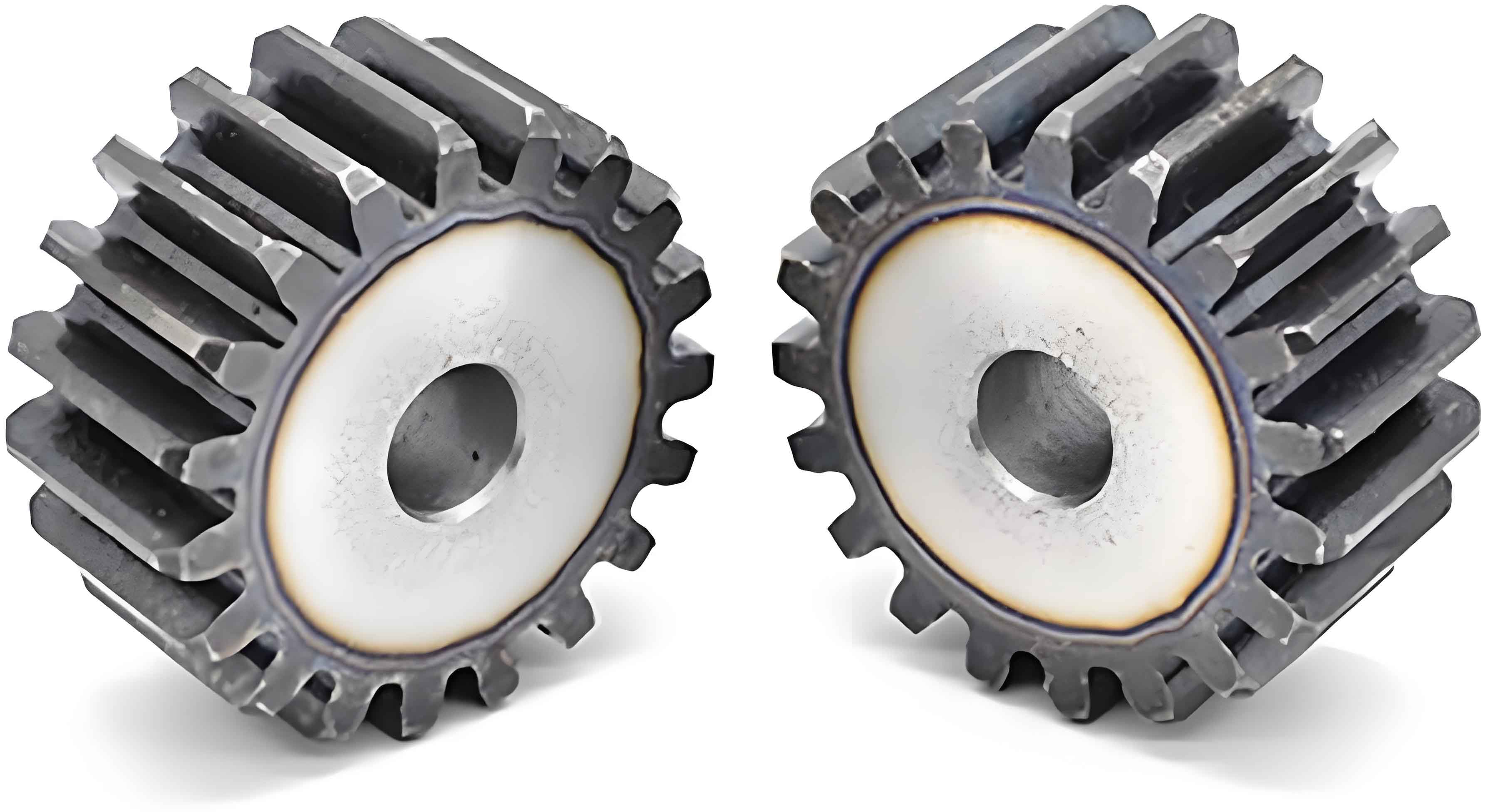
3.2.1 Small Gear Modeling
In the UG toolbar, select cylindrical gear modeling to open the “Involute Gear Modeling” dialog box. Use the “Create Gear” command and choose “Modified Gear.” In the gear creation dialog box, input the calculated geometric parameters such as module, number of teeth, pressure angle, etc. into the corresponding positions and click OK to generate the small gear.
3.2.2 Large Gear Modeling
Similar to the small gear modeling process, select the appropriate options in the toolbar, input the parameters of the large gear, and obtain the three-dimensional model of the large gear.
3.3 Gear Meshing Setup
In the gear modeling, select “Cylindrical Gear Modeling,” and in the “Involute Gear Modeling” dialog box, choose “Gear Meshing” as the gear operation mode. In the gear meshing dialog box, set the small gear as the driving gear, the large gear as the driven gear, and the centerline vector as the Y-axis.
4. Theoretical Calculation of Tooth Surface Contact Strength Based on Hertz Theory
4.1 Hertz Theory Formula
The Hertz contact theory was proposed by Hertz to solve contact mechanics problems. Although it has limitations in practical applications, it is widely used in gear contact analysis. For spur gears, the maximum contact stress at the node can be calculated using the Hertz theory formula:
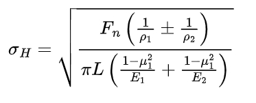
where σH is the contact stress, Fn is the normal load (Fn=2T/dcosα), T is the torque, L is the contact line length (L=3b/4-εα), b is the tooth width, εα is the contact ratio, ρ1 and ρ2 are the curvature radii of the two tooth profiles at the node, μ1 and μ2 are the Poisson’s ratios, and E1 and E2 are the elastic moduli of the two gears.
When E1=E2=E and μ1=μ2=0.3, the maximum stress formula can be simplified to:
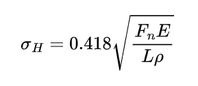
where ρ=ρ1ρ2/ρ1+ρ2
4.2 Calculation of Contact Stress for High-Modification Cylindrical Spur Gear Pair
After looking up the table and calculating εα=1.68. Substituting E1=E2=2.06✖10^11Pα and the parameters in Table 3 into the formula, the calculated contact stress is σH=283.367MPα , and the contact line length L=32.2858mm.
5. Finite Element Analysis Based on Ansys Workbench
5.1 Material Assignment
Both the small and large gears are assigned a structural steel material with a density of 7850kg/m^3, an elastic modulus of 2.06✖10^11Pα, and a Poisson’s ratio of 0.3.
5.2 Mesh Generation
The two gears are meshed using 3D tetrahedral elements. To focus on the stress situation of the meshing teeth, the gear contact parts are encrypted with a size of 2mm. After meshing, a total of 1,175,893 nodes and 825,316 elements are generated.
5.3 Application of Boundary Conditions and Loads
In the finite element environment, boundary conditions and loads are applied. The small gear is set as the driving gear, and the large gear is the driven gear. The contact type is set as frictional contact with a coefficient of 0.15. Two rotational joints are created around the Z-axis. A rotational speed of 1rad/s is added to the small gear, and a torque load of 500N/m is added to the large gear in the same direction as the small gear. The load step control is set with the definition basis as substeps, the minimum substep as 20, and the maximum substep as 200 for transient dynamic analysis of the high-modification cylindrical spur gears.
5.4 Simulation Results
The transient analysis results of the high-modification cylindrical spur gear.
From the analysis results, the maximum contact stress of the two gears in the simulation is 287.55MPa, located on the contact surface of the two teeth. Comparing the theoretical value of 283.367MPa calculated by the Hertz formula, the error is small and meets the working condition requirements.
6. Conclusion
6.1 Summary of Research Results
- Through the transmission calculation of high-modification cylindrical spur gear, the geometric parameters of the meshing gears are obtained, and the three-dimensional modeling of the gears is achieved using UG (CAD), providing a solution for the design and optimization of similar mechanical products.
- The transient dynamic analysis of the gears using Ansys Workbench, through material assignment, 3D mesh generation, load and constraint settings, obtains the stress and displacement contours of the meshing gears, intuitively showing the force situation during gear movement.
- The theoretical contact stress value of the gears is calculated using the Hertz formula and compared with the maximum equivalent stress in the simulation. The small error meets the working condition requirements, indicating that the UG (CAD) three-dimensional parameterized modeling can meet the dynamic characteristics requirements of the high-modification cylindrical spur gear meshing transmission.
6.2 Significance and Application Prospect
This research has important theoretical and practical significance. Theoretically, it enriches the research content of high-modification cylindrical spur gears and provides a theoretical basis for further research. Practically, it can guide the design and optimization of high-modification cylindrical spur gears in mechanical engineering, improve the performance and lifespan of gear transmissions, and reduce product development costs and design cycles. In the future, this research can be further extended to the study of more complex gear systems and different working conditions to provide more comprehensive technical support for the development of mechanical engineering.