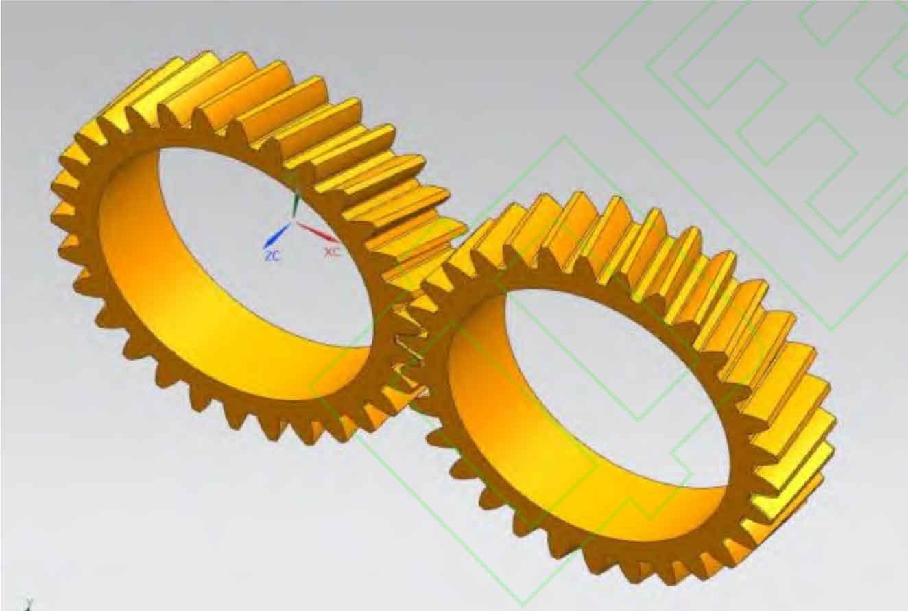
The mathematical model of helical gear is established based on the meshing principle of helical gear tooth surface and the conversion principle of machining coordinate system. The software is programmed using Mathematica software to solve the three-dimensional point coordinates of the modified helical gear tooth surface. Import the generated set of tooth surface coordinate points into a 3D drawing software, and generate a 3D solid model of a helical gear by constructing sidelines, surface stitching, fillet, array, and rotational extrusion cutting. Apply the modified helical gear tooth surface points generated by Mathematica to The format of DAT is saved and imported into UG. Generate a single tooth surface through commands such as importing point sets, extending sheets, surface stitching, and chamfering, and then generate a 3D model of the modified driving wheel through commands such as array stretching and cutting, as shown in the figure.

As shown in the figure, the studied helical gear pair consists of a pair of meshing teeth composed of driving and driven wheels, and its basic parameters are shown in the table.
| Parameters | Driving wheel | Driven wheel |
| Number of teeth z | 30 | 30 |
| Modulus mn/mm | 6.5 | 6.5 |
| Pressure angle α n/(°) | 20 | 20 |
| Helix angle β/ (°) | 13(Dextral rotation) | 13(Sinistral rotation) |
| Tooth width b/mm | 53 | 53 |
| Displacement coefficient xn | 0.72 | 0.72 |
The material of the helical gear pair is 20CrMnTiH, and the elastic modulus is 𝐸=2.07 × 10² 𝑀 𝑃 𝑎, Poisson’s ratio is 0.3, and density is 𝜌=7.8 × 10² 𝑘 𝑔/𝑚 2, tensile strength 1483MPa, yield strength 1292MPa, allowable contact stress 745MPa, allowable bending stress 510MPa.
