
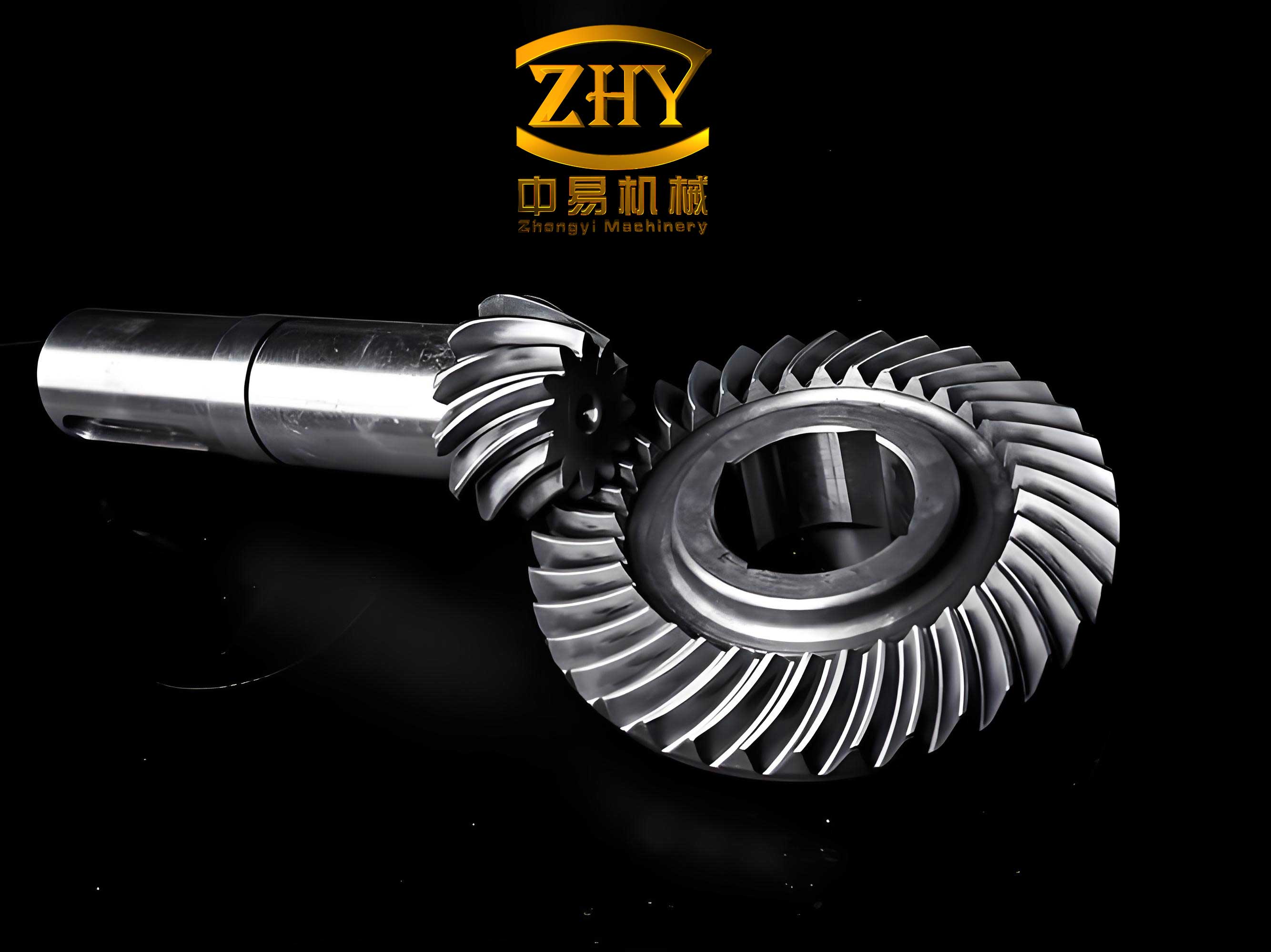
As a fundamental transmission component, the spiral bevel gear plays a critical role in transmitting motion and power between intersecting axes, finding extensive applications in industries such as aviation, marine, automotive, tractors, and machine tools. The accurate three-dimensional modeling of spiral bevel gears is essential for design validation, performance analysis, and manufacturing preparation. Traditional methods for modeling spiral bevel gears often rely on gear meshing principles and require complex mathematical derivations, extensive data processing, and deep theoretical knowledge, which can be challenging for engineers. Therefore, developing an efficient and accessible modeling approach using modern CAD software like Pro/Engineer (Pro/E) is of significant practical importance. In this article, I will detail a method for creating precise three-dimensional models of standard involute spiral bevel gears in Pro/E, focusing on parametric design to ensure accuracy and flexibility.
The core of this modeling approach lies in establishing parametric relationships between gear dimensions and fundamental parameters such as modulus, number of teeth, and pressure angle. By leveraging Pro/E’s equation-driven curves and relation features, we can generate accurate involute profiles and automate the model generation for various spiral bevel gear configurations. This not only streamlines the design process but also facilitates subsequent finite element analysis, motion simulation, and CNC programming. Below, I will walk through the methodology step by step, incorporating tables and formulas to summarize key relationships and procedures.
Design Parameters and Their Interrelationships
To begin, we must define the basic design parameters for the spiral bevel gear. These parameters are interconnected through geometric and trigonometric relations, which can be encapsulated in Pro/E’s relation editor. The primary inputs include the modulus (m), number of teeth (z), pressure angle (α), face width (B), addendum coefficient (ha*), dedendum coefficient (c*), and spiral angle at the mean cone distance (β). Additional parameters, such as the number of teeth on the mating gear (zasm), are needed to calculate the pitch cone angle. The following table summarizes the key design parameters and their calculation formulas, which are essential for building a parametric model.
| Parameter Symbol | Parameter Name | Calculation Formula |
|---|---|---|
| m | Modulus | Given input |
| z | Number of teeth | Given input |
| zasm | Number of teeth on mating gear | Given input |
| α | Pressure angle | Given input (typically 20°) |
| B | Face width | Given input |
| ha* | Addendum coefficient | Given input (typically 1) |
| c* | Dedendum coefficient | Given input (typically 0.25) |
| δ | Pitch cone angle | $$δ = \arctan\left(\frac{z}{z_{\text{asm}}}\right)$$ |
| D | Pitch diameter at large end | $$D = m \cdot z$$ |
| Db | Base diameter at large end | $$D_b = D \cdot \cos(α)$$ |
| ha | Addendum at large end | $$h_a = (h_a^* + x) \cdot m$$, where x is profile shift coefficient (0 for standard gears) |
| hf | Dedendum at large end | $$h_f = (h_a^* + c^* – x) \cdot m$$ |
| Da | Tip diameter at large end | $$D_a = D + 2 \cdot h_a \cdot \cos(δ)$$ |
| Df | Root diameter at large end | $$D_f = D – 2 \cdot h_f \cdot \cos(δ)$$ |
| Rx | Cone distance | $$R_x = \frac{D}{2 \cdot \sin(δ)}$$ |
| θa | Addendum angle | $$θ_a = \arctan\left(\frac{h_a}{R_x}\right)$$ |
| θf | Dedendum angle | $$θ_f = \arctan\left(\frac{h_f}{R_x}\right)$$ |
| δa | Tip cone angle | $$δ_a = δ + θ_a$$ |
| δf | Root cone angle | $$δ_f = δ – θ_f$$ |
| β | Mean spiral angle | Given input (typically 35°) |
These parameters form the foundation for constructing the gear geometry. In Pro/E, we can input these as parameters and use relations to drive the model, allowing for quick modifications by simply changing the basic inputs. This parametric approach is particularly beneficial when designing families of spiral bevel gears with different sizes or tooth counts.
Step-by-Step Modeling Procedure in Pro/E
The modeling process involves creating reference geometries, generating involute curves at both the large and small ends, constructing the tooth profile, and performing a sweep blend operation to form the three-dimensional tooth shape. I will describe each step in detail, emphasizing the use of equations and parametric controls.
1. Creating Basic Reference Curves and Planes
First, we establish the coordinate system and key reference planes. Start by offsetting the default TOP plane by a distance calculated as D/(2·tan(δ)) to position the apex of the pitch cone. Then, create a datum axis A1 through this apex point and a datum point PNT0 at the intersection of the axis and the offset plane. In the FRONT plane, sketch four lines emanating from PNT0: the pitch cone line, root cone line, base cone line, and tip cone line. These lines represent the generators of the respective cone surfaces. Dimension the pitch cone line with an angle δ relative to the horizontal and a length corresponding to D/2. Similarly, dimension the tip and root cone lines to lengths Da/2 and Df/2, respectively. The base cone line is dimensioned to Db/2. Additionally, sketch the back cone lines at both the large and small ends, perpendicular to the pitch cone line and separated by the face width B. This setup creates the foundational skeleton for the spiral bevel gear.
Next, create two auxiliary datum planes (DTM2 and DTM3) perpendicular to the FRONT plane and passing through the back cone lines. On these planes, sketch the base circles, tip circles, root circles, and pitch circles for both the large and small ends. These circles serve as the basis for generating the involute tooth profiles. Also, draw vertical center lines on these sketches to aid in creating coordinate systems later.
2. Generating Involute Curves Using Parametric Equations
The accuracy of the spiral bevel gear model hinges on the precise generation of involute curves. In Pro/E, we can create datum curves from equations. For both the large and small ends, we define a coordinate system (CS1 for large end, CS3 for small end) with its origin at the intersection of the gear axis and the respective auxiliary plane, and the Z-axis perpendicular to that plane. The involute curve is then defined in Cartesian coordinates using a parameter t that ranges from 0 to 1. The parametric equations for the involute are derived from the geometry of the base circle:
Let r be the base radius (r = Db/2 for large end, or adjusted for small end), and let θ be the involute angle parameterized by t. The equations are:
$$ x = r \cdot \cos(\theta) + r \cdot \theta \cdot \sin(\theta) $$
$$ y = r \cdot \sin(\theta) – r \cdot \theta \cdot \cos(\theta) $$
$$ z = 0 $$
where θ is expressed as: $$ \theta = t \cdot \frac{60}{\text{scale}} $$ (with scale adjusted to ensure full tooth profile). In Pro/E’s equation editor, we input these directly. To ensure symmetry about the FRONT plane (which bisects the tooth space), we create two involute segments: one for the left flank and one for the right flank, mirrored across the tooth centerline. This ensures the tooth profile is theoretically correct on the developed back cone surface.
3. Constructing the Tooth Profile and Sweep Trajectory
With the involute curves defined, we proceed to create the complete tooth profile. First, establish datum planes DTM4 and DTM5 based on the tooth thickness angles. The tooth thickness at the large end is determined by the circular pitch, which is πm. Using relations, we calculate the angle subtended by half the tooth thickness on the pitch circle. Then, mirror the involute curves about DTM5 to form the opposite flank. By rotating these curves appropriately, we obtain closed profiles for the tooth at both the large and small ends. These profiles will serve as sections for the sweep blend feature.
The spiral path of the tooth is defined by a three-dimensional curve. We create a datum plane DTM6 oriented relative to the pitch cone line, and on this plane, sketch an arc whose radius corresponds to the cutter radius used in generating spiral bevel gears. The arc’s angle is related to the mean spiral angle β. This arc is then projected onto a conical surface (the pitch cone) to create the sweep trajectory. The projection ensures the trajectory follows the curved path characteristic of spiral bevel gears, imparting the desired spiral teeth. The trajectory curve is critical for achieving the correct tooth orientation and contact pattern.
4. Performing Sweep Blend and Pattern Completion
Using the sweep blend feature in Pro/E, we select the projected trajectory and specify the two tooth profiles (at large and small ends) as sections. Pro/E interpolates between these sections along the trajectory to generate a single tooth solid. This feature automatically handles the transition from the large end to the small end, maintaining the involute profile and spiral curvature. After creating one tooth, we use the pattern tool to replicate it around the gear axis. The number of instances is set to z-1 (since one tooth is already created), and the rotation angle between instances is 360/z degrees. This yields the full set of teeth, resulting in a complete spiral bevel gear model.
Parametric Flexibility and Design Variations
A major advantage of this method is its parametric nature. By defining all dimensions through relations linked to the basic parameters (m, z, α, etc.), we can quickly generate spiral bevel gears of different sizes and specifications. For example, to design a gear with a different modulus, we simply update the value of m, and all related dimensions—such as diameters, addendum, dedendum, and even the involute curves—recalculate automatically. This is summarized in the following table, which shows how key dimensions scale with modulus and tooth number for spiral bevel gears.
| Dimension | Dependency | Example Relation |
|---|---|---|
| Pitch diameter D | Linear with m and z | $$D = m \cdot z$$ |
| Base diameter Db | Linear with m and z, scaled by cos(α) | $$D_b = m \cdot z \cdot \cos(α)$$ |
| Tip diameter Da | Linear with m, depends on addendum | $$D_a = m \cdot z + 2 \cdot m \cdot (h_a^* + x) \cdot \cos(δ)$$ |
| Root diameter Df | Linear with m, depends on dedendum | $$D_f = m \cdot z – 2 \cdot m \cdot (h_a^* + c^* – x) \cdot \cos(δ)$$ |
| Cone distance Rx | Inversely proportional to sin(δ) | $$R_x = \frac{m \cdot z}{2 \cdot \sin(δ)}$$ |
| Tooth thickness angle | Inversely proportional to z | $$\text{Angle} = \frac{180}{z}$$ degrees |
Moreover, this approach can be adapted for both non-equivalent and equivalent clearance spiral bevel gears. For equivalent clearance gears, the dedendum angle is adjusted so that the clearance is constant along the tooth depth. This can be incorporated by modifying the relation for θf or by using different coefficients. The flexibility extends to including profile shift (x) for customized tooth geometry, which is common in advanced spiral bevel gear design to avoid undercut or optimize strength.
Mathematical Foundation of Involute Generation
The involute curve is fundamental to gear tooth design, ensuring conjugate action and constant velocity ratio. For a spiral bevel gear, the involute is developed on the back cone, which approximates a spherical surface. The parametric equations used in Pro/E are derived from the definition of an involute: the curve traced by a point on a taut string as it unwinds from a base circle. Mathematically, for a base circle of radius rb, the involute coordinates are given by:
$$ x = r_b (\cos(\phi) + \phi \sin(\phi)) $$
$$ y = r_b (\sin(\phi) – \phi \cos(\phi)) $$
where φ is the involute angle in radians. In Pro/E, we parameterize φ as a function of t to control the curve length. For the large end, rb = Db/2, and for the small end, rb is scaled according to the cone distance. The small end base radius can be calculated as:
$$ r_{b,\text{small}} = \frac{D_b – 2 \cdot B \cdot \sin(δ_b)}{2 \cdot \cos(δ)} $$
where δb is the base cone angle. These equations ensure that the involute profile is consistent across the face width, which is crucial for proper meshing of spiral bevel gears.
Applications and Benefits of Accurate 3D Models
Accurate three-dimensional models of spiral bevel gears enable numerous downstream applications. Once the model is built in Pro/E, it can be exported for finite element analysis (FEA) to evaluate stress distributions, contact patterns, and fatigue life. It can also be used in dynamic simulation software to assess vibration and noise characteristics. Furthermore, the model serves as a direct input for CNC machining, either via CAM modules within Pro/E or through neutral formats like STEP or IGES. This integration reduces errors and speeds up the manufacturing process for spiral bevel gears, which are often critical components in power transmission systems.
The parametric design approach also supports optimization studies. By linking the Pro/E model to optimization tools, designers can automatically vary parameters like modulus, pressure angle, or spiral angle to achieve desired performance metrics, such as minimum weight or maximum load capacity. This is especially valuable in aerospace and automotive industries, where spiral bevel gears must meet stringent efficiency and durability requirements.
Conclusion
In summary, the method described herein provides a robust and efficient way to create three-dimensional models of involute spiral bevel gears using Pro/Engineer. By leveraging parametric equations, relation-driven dimensions, and advanced features like sweep blend, we can generate accurate gear geometry that adheres to theoretical principles. The use of tables and formulas to encapsulate parameter relationships enhances clarity and reproducibility. This approach not only simplifies the design process but also allows for rapid customization and adaptation to different gear specifications. As spiral bevel gears continue to be vital in mechanical transmissions, such CAD modeling techniques will remain indispensable for engineers seeking to combine precision with productivity. Future work could extend this methodology to include tooth modifications, such as crowning or bias, to further improve the performance of spiral bevel gears in demanding applications.