
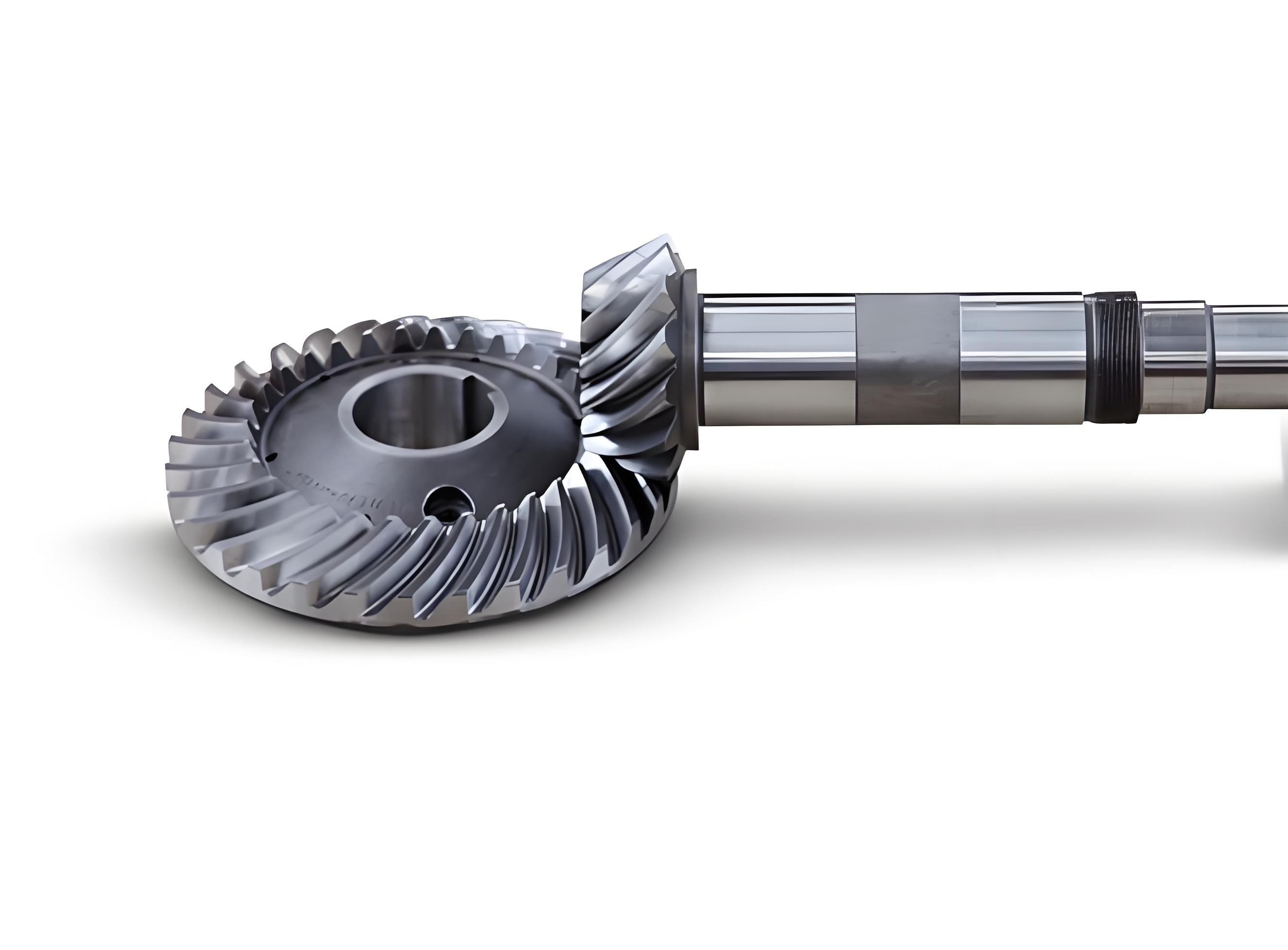
In modern mechanical engineering, spiral bevel gears are critical components due to their ability to transmit power efficiently at high speeds, under heavy loads, and with low noise levels. However, the complex spatial curved tooth profile of spiral bevel gears poses significant challenges in geometric design, transmission analysis, and manufacturing. To address these challenges, I have developed a comprehensive methodology for the three-dimensional parametric design of spiral bevel gears using advanced CAD software capabilities. This article presents my first-person perspective on the fundamental concepts, methods, and steps involved in this parametric modeling approach, which leverages sophisticated surface modeling and programming functions. The goal is to provide a useful tool for deeper research into the meshing, transmission, analysis, and machining of spiral bevel gears. Throughout this discussion, I will emphasize the importance of spiral bevel gears in various applications and how parametric design can enhance their development.
The design process begins with a geometric model of a spiral bevel gear, which consists of key nodes and curves that define the tooth shape. As illustrated in the following figure, the geometry includes points such as P1 to P10, which represent critical locations on a single tooth. These points are connected by lines that form surface patches, ultimately creating the solid tooth geometry. The entire gear is constructed by copying and arraying these teeth. The core of this modeling approach lies in generating these lines, which include spherical involutes, arcs, and spatial curves. Understanding this geometric foundation is essential for implementing parametric design effectively.
To achieve parametric design, I utilized a CAD environment with robust surface modeling and programming tools. The process involves defining mathematical equations for each curve based on gear parameters such as module, number of teeth, spiral angle, pressure angle, and cutter radius. By inputting these parameters, the three-dimensional model is automatically generated, allowing for rapid prototyping and analysis. In the following sections, I will detail the methods and steps for creating each curve and surface, along with the parametric implementation. This approach not only streamlines the design of spiral bevel gears but also facilitates further engineering applications like finite element analysis and computer-aided manufacturing.
Geometric Model Overview
The geometric model of a spiral bevel gear is based on a set of nodes that describe the tooth轮廓. These nodes are interconnected by lines, which can be categorized into spherical involutes, arcs, and spatial curves. Specifically, for a single tooth, there are 12 lines: 4 spherical involutes, 4 arcs, and 4 spatial curves. The lines are generated in a sequence that builds up the tooth surface from the root to the tip and from the large end to the small end. The table below summarizes the key nodes and their corresponding curve types, which are essential for understanding the modeling process.
| Node | Curve Type | Description |
|---|---|---|
| P1 to P2 | Spherical Involute | Large-end tooth profile on one side |
| P7 to P8 | Spherical Involute | Large-end tooth profile on the opposite side |
| P2 to P8 | Arc | Large-end tip arc |
| P1 to P3 | Spatial Curve | Root cone tooth profile on one side |
| P7 to P9 | Spatial Curve | Root cone tooth profile on the opposite side |
| P2 to P4 | Spatial Curve | Tip cone tooth profile on one side |
| P8 to P10 | Spatial Curve | Tip cone tooth profile on the opposite side |
The generation of these curves relies on spherical coordinates, where each point is defined by a radial distance, a cone angle, and a rotation angle. This coordinate system is ideal for modeling spiral bevel gears because it aligns with their conical geometry. In parametric design, these coordinates are expressed as functions of variables, allowing for automatic updates when input parameters change. The subsequent sections will delve into the mathematical equations and steps for creating each curve type, emphasizing how spiral bevel gears can be accurately represented in a digital environment.
Parametric Design Methods and Steps
The parametric design of spiral bevel gears involves a systematic approach to generating curves and surfaces. I will describe each step in detail, starting with the large-end spherical involutes and proceeding to the complete gear model. This process ensures that all geometric elements are correctly defined and can be modified through parameter inputs.
Large-End Spherical Involutes
The large-end spherical involutes form the core of the tooth profile on the gear’s outer diameter. In spherical coordinates, the position of a point on the involute is given by three components: the radial distance \( \rho \), the cone angle \( \theta \), and the rotation angle \( \phi \). These are expressed as functions of a parameter \( t \), which varies from 0 to 1. For spiral bevel gears, the spherical involute equation is derived from the base cone geometry. The radial distance is constant and equal to the sphere radius \( R \), which relates to the pitch diameter \( D \) and pitch cone angle \( \delta_1 \) as follows:
$$ R = \frac{D}{2 \sin \delta_1} $$
The cone angle \( \theta \) varies from the root cone angle \( \delta_f \) to the tip cone angle \( \delta_a \). The rotation angle \( \phi \) for any point on the spherical involute, denoted as \( \beta_{p\text{球}} \), is calculated using the formula:
$$ \beta_{p\text{球}} = \frac{1}{\sin \delta_b} \arccos\left[\frac{\cos \delta_p}{\cos \delta_b}\right] – \arccos\left[\frac{\tan \delta_b}{\tan \delta_p}\right] $$
where \( \delta_b \) is the base cone angle, and \( \delta_p \) is the cone angle at point \( p \). In practice, to generate the involute curve from P1 to P2, I use the following parametric equations in the CAD software:
$$ \rho = R, \quad \theta = \delta_f + t(\delta_a – \delta_f), \quad \phi = \frac{\arccos\left[\frac{\cos(\delta_f + t(\delta_a – \delta_f))}{\cos \delta_b}\right]}{\sin \delta_b} + \arccos\left[\frac{\tan \delta_b}{\tan(\delta_f + t(\delta_a – \delta_f))}\right] $$
Similarly, for the opposite side involute from P7 to P8, the \( \phi \) value is negated and adjusted by the root circle tooth thickness angle. This ensures that both sides of the tooth are symmetric. The table below summarizes the parameters involved in generating spherical involutes for spiral bevel gears.
| Parameter | Symbol | Description |
|---|---|---|
| Sphere Radius | \( R \) | Constant radial distance in spherical coordinates |
| Root Cone Angle | \( \delta_f \) | Cone angle at the root of the tooth |
| Tip Cone Angle | \( \delta_a \) | Cone angle at the tip of the tooth |
| Base Cone Angle | \( \delta_b \) | Angle of the base cone for involute generation |
| Parameter | \( t \) | Variable from 0 to 1 for curve interpolation |
Large-End Tip and Root Arcs
After generating the involutes, the next step is to create the large-end tip and root arcs, which connect the endpoints of the involutes. These arcs are circular segments on the tip and root cones. In spherical coordinates, the tip arc from P2 to P8 is defined by a constant cone angle \( \theta = \delta_a \) and a varying rotation angle \( \phi \). The parametric equations are:
$$ \rho = R, \quad \theta = \delta_a, \quad \phi = \phi_{z} + t \cdot \phi_{\text{hou}} $$
where \( \phi_{z} \) is the rotation angle at one endpoint, and \( \phi_{\text{hou}} \) is the tooth thickness angle on the tip cone, which is calculated based on gear geometry. Similarly, the root arc from P1 to P7 is generated using:
$$ \rho = R, \quad \theta = \delta_f, \quad \phi = \phi_{gz} + t \cdot \phi_{\text{ghou}} $$
with \( \phi_{gz} \) and \( \phi_{\text{ghou}} \) being the root cone counterparts. These arcs ensure a smooth transition between tooth profiles and are essential for accurate modeling of spiral bevel gears.
Tooth Profile Curves on Tip and Root Cones
The tooth profile curves on the tip and root cones are spatial curves that account for the spiral shape of the teeth. These curves are generated based on the cutter geometry used in manufacturing. According to the principle of the imaginary crown gear, the cutter disk center is positioned relative to the spherical coordinate origin. The distance \( L_1 \) between the cutter center and the coordinate origin is calculated using the cosine theorem:
$$ L_1 = \sqrt{L_0^2 + r_d^2 – 2 L_0 r_d \sin(\lambda_{xj})} $$
where \( L_0 \) is the midpoint cone distance, \( r_d \) is the cutter radius, and \( \lambda_{xj} \) is the nominal spiral angle. For any point on these curves, the radial distance \( \rho \) and rotation angle \( \phi \) are derived from geometric projections. First, the angle \( \zeta \) corresponding to the outermost and innermost points is determined, and then the offset angle \( Q \) is computed:
$$ \tan(\zeta) = \frac{r_d \sin \xi}{L_1 + r_d \cos \xi}, \quad Q = \frac{\zeta}{\sin \delta_1} $$
Here, \( \xi \) is an intermediate angle based on the cone distance and cutter radius. The radial distance for any point is given by:
$$ \rho = L_1 \cos(\zeta) + \sqrt{r_d^2 – L_1^2 \sin^2(\zeta)} $$
Using these equations, the root cone tooth profile curve from P1 to P3 is generated with:
$$ \rho = L, \quad \theta = \delta_f, \quad \phi = \phi_{gz} + Q_1 – \frac{\zeta}{\sin \delta_1} $$
where \( L \) is the computed radial distance from the above formula. The opposite side curve from P7 to P9 is obtained by adding the root tooth thickness angle \( \phi_{\text{ghou}} \) to the \( \phi \) expression. Similarly, the tip cone curves from P2 to P4 and P8 to P10 are created using \( \theta = \delta_a \) and appropriate \( \phi \) adjustments. This method ensures that the spiral bevel gears have accurate tooth profiles that match manufacturing constraints.
Small-End Tooth Surface Curves
The small-end tooth surface curves are derived from the large-end curves by adjusting the radial distance and rotation angles. Since the tooth thickness angle remains constant from the large end to the small end, the small-end spherical involutes and arcs are generated using similar equations but with a reduced radial distance. Specifically, for the small end, the radial distance is \( \rho = R – b \), where \( b \) is the face width. The cone angles \( \theta \) are the same as for the large end, and the rotation angles \( \phi \) are adjusted by adding or subtracting \( (Q_1 – Q_2) \), depending on the hand of the spiral. This ensures consistency in tooth geometry across the gear width. The parametric equations for the small-end involutes are:
$$ \rho = R – b, \quad \theta = \delta_f + t(\delta_a – \delta_f), \quad \phi = \phi_{\text{large}} \pm (Q_1 – Q_2) $$
where \( \phi_{\text{large}} \) is the \( \phi \) value from the large-end curve. This approach allows for the complete definition of the tooth surface from end to end, which is crucial for the overall design of spiral bevel gears.
Building Tooth Surfaces and the Complete Gear
Once all curves are generated, the next step is to create surfaces from them. In the CAD software, I use the boundary blend function to create surfaces by selecting sequences of curves, such as an involute and adjacent arcs. For example, a tooth surface patch can be formed by blending the large-end involute, tip arc, and root arc. After creating individual surfaces, they are merged into a single continuous surface using surface merge operations. This process is repeated for all tooth segments.
To create the entire gear, the tooth surface is first copied and then patterned around the gear axis. The number of copies equals the number of teeth, which is specified as an input parameter. Finally, a solid extrusion is performed using the quilt of surfaces to generate the three-dimensional gear body. Additional features like the central hub, bore, and keyway are added using standard modeling techniques. The parametric nature of this process allows for quick modifications; for instance, changing the number of teeth automatically updates the pattern and regenerates the gear. This efficiency is vital for designing custom spiral bevel gears for various applications.
Parametric Implementation
To achieve full parametric control, I integrate the design steps into a program within the CAD software. This involves defining input variables, relationships, and conditional statements. The input variables include key gear parameters such as module \( m \), number of teeth \( Z \), spiral angle \( \lambda \), pressure angle \( \alpha \), and cutter radius \( r_d \). These are declared in the program’s input section. Relationships are then established to compute derived parameters like pitch diameter \( D \), cone angles, and tooth thickness angles. For example, the pitch diameter is calculated as \( D = m \cdot Z \), and the pitch cone angle \( \delta_1 \) is derived based on the gear ratio.
The program also includes conditional statements to handle different geometric scenarios. Specifically, when the base cone angle \( \delta_b \) is greater than the root cone angle \( \delta_f \), the spherical involute does not extend to the root, and additional arc curves are needed to fill the gap. In this case, I create supplementary arcs using parametric equations similar to those for the tip and root arcs. The program checks the relative sizes of \( \delta_b \) and \( \delta_f \) and activates the appropriate curve generation routines. This ensures robust modeling for all types of spiral bevel gears.
The table below summarizes the key input parameters and their roles in the parametric design of spiral bevel gears.
| Parameter | Symbol | Typical Value Range | Description |
|---|---|---|---|
| Module | \( m \) | 1–10 mm | Determines tooth size and pitch |
| Number of Teeth | \( Z \) | 10–50 | Defines the gear’s tooth count |
| Spiral Angle | \( \lambda \) | 20–45 degrees | Controls the curvature of the teeth |
| Pressure Angle | \( \alpha \) | 20 degrees | Affects tooth strength and meshing |
| Cutter Radius | \( r_d \) | 50–200 mm | Influences tooth profile shape |
| Face Width | \( b \) | 10–100 mm | Width of the gear along the cone |
| Shaft Angle | \( \Sigma \) | 90 degrees | Angle between gear axes in a pair |
By encapsulating the entire design logic in a program, users can simply input these parameters to generate a customized spiral bevel gear model. This parametric implementation significantly reduces design time and minimizes errors, making it a powerful tool for engineers working with spiral bevel gears.
Special Case: Base Cone Larger Than Root Cone
In some spiral bevel gear designs, the base cone angle \( \delta_b \) may be larger than the root cone angle \( \delta_f \). This situation requires special handling because the spherical involute, which is defined from the base cone outward, does not cover the region between the root cone and the base cone. To address this, I supplement the geometry with arc curves that bridge the gap. These arcs are generated using spherical coordinate equations with the cone angle varying from \( \delta_f \) to \( \delta_b \). For the large end, the equations are:
$$ \rho = R, \quad \theta = \delta_f + t(\delta_b – \delta_f), \quad \phi = 0 \text{ or } \phi = \phi_{\text{jzchang}} $$
where \( \phi_{\text{jzchang}} \) is a calculated rotation angle based on tooth thickness. For the small end, the radial distance is reduced to \( \rho = R – b \), and the rotation angles are adjusted by \( (Q_1 – Q_2) \). After generating these arcs, I use composite curve functions to connect them with the existing involutes, ensuring a smooth tooth profile. The rest of the modeling process follows the same steps as for the standard case. This flexibility allows the parametric design method to accommodate a wide range of spiral bevel gear configurations, enhancing its applicability in diverse engineering projects.
Results and Examples
Using the described parametric design methodology, I have successfully generated three-dimensional models of spiral bevel gears with various specifications. For instance, a pair of mating gears with module \( m = 5 \, \text{mm} \), pinion teeth \( Z_1 = 15 \), gear teeth \( Z_2 = 30 \), and spiral angle \( \lambda = 35^\circ \) can be created efficiently. The models exhibit accurate tooth geometries and proper meshing characteristics, as verified through interference checks and kinematic simulations. The ability to quickly alter parameters and regenerate models facilitates iterative design and optimization. Below is a summary of key outputs from the parametric design process for spiral bevel gears.
| Gear Pair | Parameters | Generated Model Features |
|---|---|---|
| Pinion and Gear | \( m=5, Z_1=15, Z_2=30, \lambda=35^\circ \) | Full 3D solid model with accurate tooth surfaces |
| Custom Gear | \( m=3, Z=20, \lambda=25^\circ, r_d=100 \, \text{mm} \) | Adapted tooth profiles based on cutter geometry |
| High-Ratio Set | \( m=4, Z_1=10, Z_2=40, \lambda=40^\circ \) | Models suitable for finite element analysis |
These results demonstrate the effectiveness of the parametric approach in producing reliable digital prototypes of spiral bevel gears. The models can be exported for further analysis, such as stress simulation or manufacturing planning, thereby supporting the entire product development cycle.
Conclusion and Future Work
In this article, I have presented a comprehensive method for the three-dimensional parametric design of spiral bevel gears. By leveraging advanced CAD tools and mathematical modeling, this approach enables the automatic generation of gear geometry based on user-defined parameters. The process involves creating spherical involutes, arcs, and spatial curves, which are then assembled into surfaces and solids. Parametric implementation through programming allows for flexibility and efficiency, making it easier to design custom spiral bevel gears for various applications. The ability to handle special cases, such as when the base cone is larger than the root cone, further enhances the robustness of the method.
The parametric design of spiral bevel gears lays a foundation for numerous advanced studies. For example, the generated models can be used for finite element analysis to assess stress distribution and durability, or for computer-aided manufacturing to generate tool paths for gear cutting. Additionally, this methodology can be extended to other types of bevel gears, such as hypoid gears or curved-tooth bevel gears with constant tooth depth. Future work may involve integrating this design process with optimization algorithms to minimize noise or maximize load capacity, as well as developing real-time simulation tools for gear meshing analysis. As spiral bevel gears continue to be critical components in automotive, aerospace, and industrial machinery, advancing their parametric design will contribute significantly to engineering innovation.
Overall, the parametric design of spiral bevel gears represents a powerful intersection of geometry, mathematics, and software engineering. By automating the modeling process, engineers can focus on higher-level design challenges and accelerate the development of high-performance gear systems. I hope this detailed exposition provides valuable insights and practical guidance for researchers and practitioners working with spiral bevel gears.