| Parameters | Offset distance E/mm | Axis intersection angle σ / (°) | Number of headers Z0 | Number of teeth Z | Initial installation angle β V/(°) | Cutting edge radius RI/mm | Tooth profile pressure angle α 0/(°) | Tool direction angle σ 0/(°) | Regrinding angle Ψ/ (°) | Rear angle of main blade γ a/(°) | Anterior horn γ s/(°) |
| Hypoid gear pinion concave | 38.1 | 90 | 17 | 11 | -21.176 | 1324.49 | 19.445 | 22.93 | 4.705 | 12.673 | 9.642 |
| Hypoid gear pinion convex | 38.1 | 90 | 17 | 11 | -10.588 | 1305.95 | 20.554 | 22.93 | 4.935 | 13.389 | 10.320 |
| Hypoid gear wheel concave | 38.1 | 90 | 17 | 47 | 10.588 | 1030.74 | 17.485 | 22.93 | 4.304 | 12.678 | 10.290 |
| Hypoid gear wheel convex | 38.1 | 90 | 17 | 47 | 21.176 | 1276.45 | 22.515 | 22.93 | 5.319 | 13.382 | 9.601 |
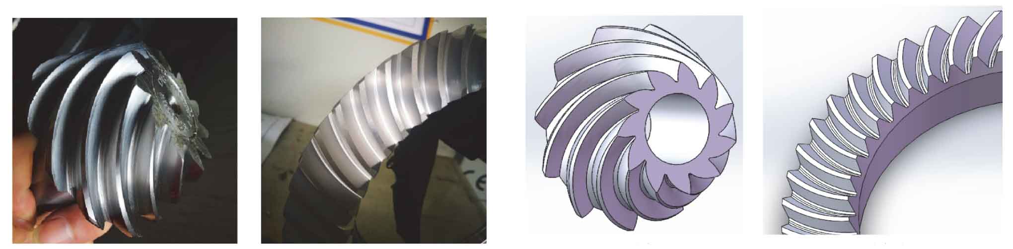
According to the basic parameters and machine tool processing parameters of Oricon hypoid gear shown in Tables 1 and 2, the actual hypoid gear is processed by importing kimos software into C27 machine tool, and compared with the mathematical model of large and small gears derived from the tooth surface equation, as shown in Figure 1.
| Parameters | Knife angle i/ (°) | Knife angle j/ (°) | Radial tool position SR/mm | Initial shaking table angle q/ (°) | Vertical wheel position Em/mm | Bed B / mm | Horizontal wheel position A/mm | Root cone angle of machine tool γ/ (°) | Roll ratio Ra |
| Hypoid gear pinion | 3.3325 | 146.9405 | 119.6391 | 52.6673 | 39.8352 | -12.2486 | 3.1156 | 23.4453 | 4.722168 |
| Hypoid gear wheel | 0.0000 | 0.0000 | 122.0090 | -29.7048 | 0.0000 | 0.0000 | 0.0000 | 64.7995 | 0.000000 |
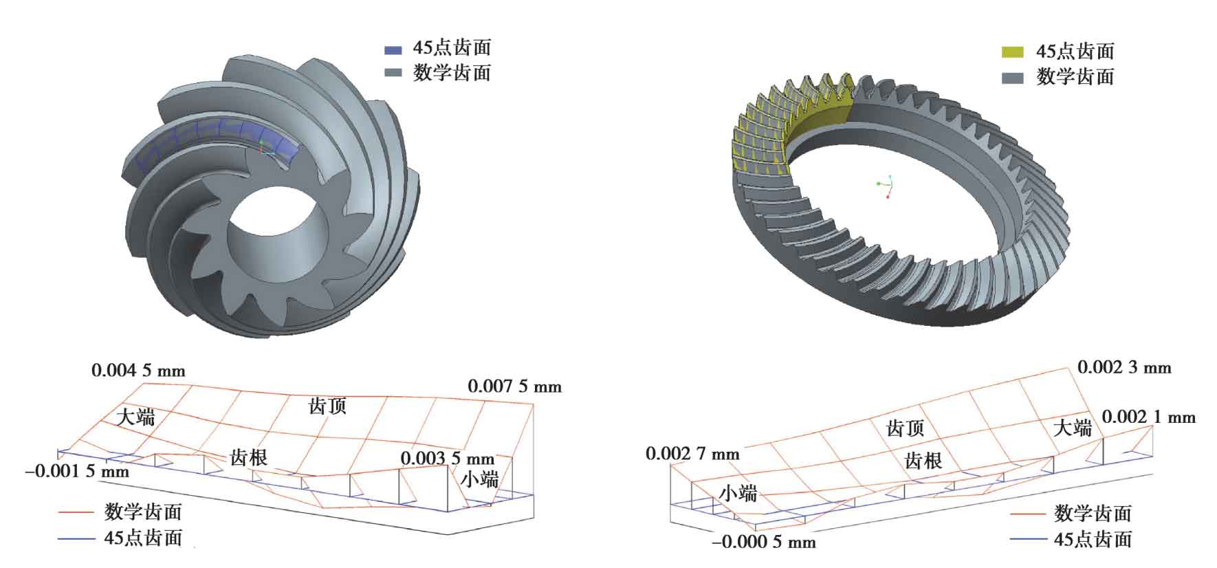
45 point tooth surface point set is obtained through kimos design module; The point set of hypoid gear is solved by calculating the mathematical model of tooth surface. Establish the mathematical tooth surface solid model of large and small wheels in Creo software, import 45 point data, and establish the comparative tooth surface, as shown in Figure 2. In Figure 2, the blue tooth surface is the tooth surface composed of 45 points of the concave theory of the small wheel, and the orange is the tooth surface composed of 45 points of the convex theory of the large wheel. The grey model is the solid model of the large and small wheel established through the derivation of the tooth surface equation. The comparative analysis shows that the large and small tooth surfaces basically coincide. Among them, the maximum error of the concave surface of the small wheel is located at the tip of the small end offset tooth, with a value of 0.0075mm, and the minimum error point is at the root of the big end tooth, with a value of -0.0015mm; The maximum error of the convex surface of the big wheel is 0.0023mm, which is located at the top of the eccentric tooth at the small end, and the minimum error is -0.0005mm, which is located at the root of the eccentric tooth at the big end.