
In modern manufacturing, gear milling is a critical process for producing high-precision spiral bevel gears used in aerospace, automotive, and industrial applications. The complexity of gear milling involves nonlinear interactions between thermal, mechanical, and dynamic factors, making it challenging to analyze through experimental methods alone. Experimental approaches are often time-consuming and costly, and they fail to capture real-time physical quantities like stress, strain, and temperature distributions during cutting. Therefore, I turned to finite element analysis (FEA) as a powerful tool to simulate and optimize gear milling processes. In this study, I developed a comprehensive three-dimensional FEA model to investigate stress distributions and cutting mechanics in gear milling, with a focus on the effects of tool geometry and cutting parameters. By leveraging advanced simulation techniques, I aimed to provide insights into process optimization and enhance the efficiency of gear manufacturing.
The foundation of this work lies in establishing accurate geometric models for both the gear blank and the cutting tool. Gear milling, particularly for spiral bevel gears, mimics the meshing of a hypothetical gear pair, where the cutter represents a tooth of a imaginary gear. As the workpiece rotates relative to the cutter, a tooth slot is formed through a conjugate surface generation process. I based my model on typical industrial parameters, which I summarized in the table below to ensure reproducibility and clarity. These parameters include gear dimensions, cutter specifications, and machine adjustments essential for simulating the gear milling process.
| Parameter | Value |
|---|---|
| Face cone angle (°) | 65.28 |
| Tooth width (mm) | 62.00 |
| Outer diameter (mm) | 305.36 |
| Number of teeth | 29 |
| Cutter diameter (mm) | 304.80 |
| Inner blade angle (°) | 25.17 |
| Outer blade angle (°) | 19.83 |
| Radial tool position (mm) | 134.65 |
| Installed root cone angle (°) | 58.00 |
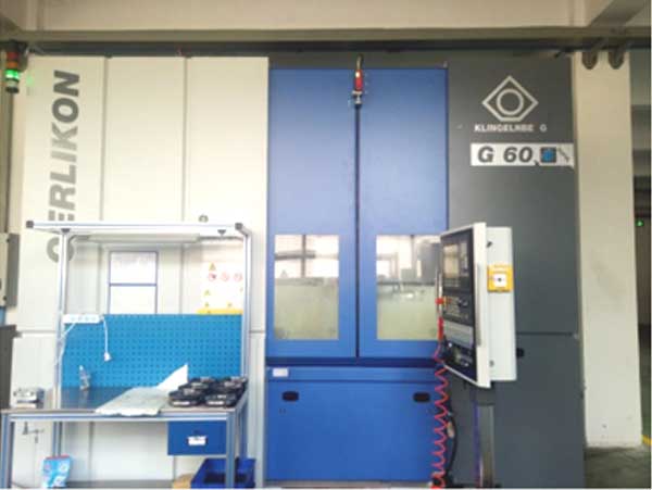
Using these parameters, I constructed a three-dimensional model in a CAD environment, which I then imported into ABAQUS/Explicit for finite element analysis. The initial positioning of the gear blank and cutter was critical to replicate actual gear milling conditions. I set the machine center as the coordinate origin, aligning the cutter and workpiece to simulate the cutting engagement accurately. To visualize the setup, I included an image of a typical gear milling machine below, which illustrates the complex interaction between the cutter and gear blank during gear milling operations.
With the geometric model in place, I proceeded to develop the finite element model. Gear milling involves repeated cutting actions by individual cutter teeth, so to reduce computational cost, I simplified the simulation to focus on a single tooth engagement. I extracted a segment of the gear blank where cutting occurs and a single cutter tooth, applying meshing strategies tailored for large deformations. The gear blank was meshed with C3D8R elements (8-node linear brick elements with reduced integration), with refined grids in regions expected to undergo severe deformation. The cutter, assumed rigid due to its high stiffness compared to the workpiece, was meshed with C3D4 elements (4-node tetrahedral elements). This approach ensured accuracy while managing simulation time effectively.
A key aspect of finite element modeling in gear milling is defining the material behavior under high-strain-rate conditions. I selected 40CrMnMo steel for the gear blank, a common material in gear manufacturing, and employed the Johnson-Cook constitutive model to account for thermal and strain-rate effects. The Johnson-Cook equation is expressed as:
$$ \sigma = (A + B \varepsilon^n) \left(1 + C \ln \frac{\dot{\varepsilon}}{\dot{\varepsilon}_0}\right) \left(1 – \left(\frac{T – T_{\text{room}}}{T_{\text{melt}} – T_{\text{room}}}\right)^m\right) $$
where $\sigma$ is the flow stress, $\varepsilon$ is the equivalent plastic strain, $\dot{\varepsilon}$ is the strain rate, $\dot{\varepsilon}_0$ is the reference strain rate, $T$ is the temperature, $T_{\text{room}}$ is room temperature, $T_{\text{melt}}$ is the melting temperature, and $A$, $B$, $C$, $n$, and $m$ are material constants. For 40CrMnMo, I used the parameters listed in the table below, derived from experimental data to ensure realistic simulation of gear milling stresses.
| Parameter | Value |
|---|---|
| A (MPa) | 598 |
| B (MPa) | 768 |
| C | 0.0137 |
| n | 0.2092 |
| m | 0.807 |
Another critical element in simulating gear milling is modeling the friction between the cutter and chip. I adopted a Coulomb friction model with a shear stress limit to represent the stick-slip behavior at the tool-chip interface. The friction stress $f$ is given by:
$$ f = \begin{cases}
\mu \sigma_n & \text{if } \mu \sigma_n < \tau_s^* \\
\tau_s^* & \text{if } \mu \sigma_n \geq \tau_s^*
\end{cases} $$
where $\mu$ is the friction coefficient, $\sigma_n$ is the normal stress, and $\tau_s^*$ is the maximum shear flow stress of the workpiece material. This model accurately captures the transition from sliding to sticking friction during gear milling, which influences cutting forces and tool wear.
For chip separation, I implemented a combined geometric-physical criterion based on fracture mechanics. The separation occurs when the fracture stress index $f$ exceeds 1, defined as:
$$ f = \left( \frac{\sigma_n}{\sigma_f} \right)^2 + \left( \frac{\tau_n}{\tau_f} \right)^2 $$
where $\sigma_n$ and $\tau_n$ are the normal and shear stresses at a specified distance ahead of the tool tip, and $\sigma_f$ and $\tau_f$ are the failure stresses under pure tension and shear, respectively. This criterion ensures realistic chip formation in gear milling simulations, balancing computational efficiency with physical accuracy.
I then conducted simulations to analyze the effects of tool geometry and cutting parameters on gear milling outcomes. The primary variables were tool rake angle and cutting speed, with a fixed feed rate of 0.3 mm. I examined how these factors influence cutting layer morphology, stress distribution, and main cutting force. The simulations were performed in ABAQUS/Explicit, leveraging its explicit dynamics solver for handling large deformations and contact interactions inherent in gear milling.
First, I investigated the evolution of cutting layer morphology and stress distribution during gear milling. At a cutting speed of 250 m/min and a tool rake angle of 8°, the simulation revealed that maximum equivalent stress initially concentrated at the tool tip and then propagated along the shear zone. As cutting progressed, the stress region expanded upward, aligning with the chip-tool contact area, which corresponds to the bending deformation of the chip. The von Mises stress remained constant in plastic regions, consistent with yield criteria. The final chip shape matched practical observations, validating the model’s accuracy for gear milling applications. This stress analysis highlights the intense plastic deformation involved in gear milling and underscores the importance of three-dimensional simulation over simplified 2D approaches.
Next, I explored the impact of tool rake angle on cutting layer deformation and strain. I varied the rake angle from 0° to 24° while keeping other parameters constant. The results, summarized in the table below, show that increasing the rake angle reduces both the bending curvature of the chip and the plastic strain in the cutting layer. This reduction occurs because a higher rake angle increases the shear angle, decreasing the deformation coefficient—a phenomenon aligned with established metal cutting theory. In gear milling, optimizing the rake angle can thus minimize energy consumption and improve surface quality.
| Tool Rake Angle (°) | Maximum Plastic Strain | Observation |
|---|---|---|
| 0 | 2.45 | Severe bending and high strain |
| 8 | 2.10 | Moderate deformation |
| 16 | 1.78 | Reduced strain |
| 24 | 1.52 | Minimal bending |
The main cutting force, a critical metric in gear milling, was also analyzed. I computed the average main cutting force $F_c$ using simulations and compared it with empirical estimates. For a rake angle of 0°, the simulation yielded $F_c = 5313 \, \text{N}$, which deviated by only 10.8% from the value calculated via the exponential formula:
$$ F_c = 9.81 \, C_{F_c} \, a_p^{x_{F_c}} \, f^{y_{F_c}} \, K_{F_c} \, K_{m_{F_c}} $$
where $C_{F_c}$ is a coefficient dependent on workpiece material and cutting conditions, $a_p$ is the depth of cut, $f$ is the feed rate, $x_{F_c}$ and $y_{F_c}$ are exponents, and $K_{F_c}$ and $K_{m_{F_c}}$ are correction factors. The close agreement validates the finite element model for gear milling force prediction. As shown in the table below, increasing the rake angle systematically reduced the main cutting force, due to decreased deformation resistance. This trend emphasizes the role of tool geometry in enhancing gear milling efficiency.
| Tool Rake Angle (°) | Average Main Cutting Force (N) | Percentage Reduction |
|---|---|---|
| 0 | 5313 | 0% |
| 8 | 4982 | 6.2% |
| 16 | 4675 | 12.0% |
| 24 | 4389 | 17.4% |
I also studied the effect of cutting speed on main cutting force in gear milling. With a tool rake angle fixed at 8°, I simulated speeds ranging from 200 to 1000 m/min. The results indicated a slight decrease in cutting force with higher speeds, approximately 3% over the range, as summarized in the table below. This reduction is attributed to thermal softening and strain-rate effects, though the marginal change suggests that cutting speed has a less pronounced impact compared to tool geometry in gear milling. However, increasing speed raises power requirements and tool wear, necessitating a balance in practical applications.
| Cutting Speed (m/min) | Average Main Cutting Force (N) | Observation |
|---|---|---|
| 200 | 4982 | Baseline force |
| 400 | 4920 | Minor decrease |
| 600 | 4875 | Further reduction |
| 800 | 4831 | Low force level |
| 1000 | 4805 | Minimal force |
Based on these findings, I optimized the gear milling parameters. For tool rake angle, a value of 20° is recommended as it balances cutting force reduction with tool durability, especially for hard materials like cemented carbide used in gear milling cutters. For cutting speed, I advise selecting the highest feasible value based on machine capabilities and productivity needs, as higher speeds slightly reduce forces but may accelerate tool wear. These optimizations aim to improve the overall efficiency and quality of gear milling processes.
In conclusion, this study demonstrates the efficacy of three-dimensional finite element simulation for analyzing gear milling processes. I successfully modeled the complex interactions in gear milling, incorporating advanced techniques like the Johnson-Cook constitutive law, Coulomb friction, and a fracture-based chip separation criterion. The simulations revealed that tool rake angle significantly influences cutting layer deformation and main cutting force, while cutting speed has a modest effect. The insights gained provide a robust framework for selecting and optimizing gear milling parameters, ultimately enhancing manufacturing performance. Future work could extend this approach to include thermal effects and tool wear predictions, further refining gear milling simulations for industrial applications.
To reiterate, gear milling is a pivotal operation in gear production, and finite element analysis offers a powerful means to dissect its intricacies. By leveraging three-dimensional models, I overcame the limitations of two-dimensional simulations, achieving a more realistic representation of stress and deformation. This methodology not only validates theoretical concepts but also paves the way for data-driven optimization in gear manufacturing. As industries demand higher precision and efficiency, such simulations will become indispensable for advancing gear milling technologies.
Throughout this work, I emphasized the importance of accurate material modeling and contact definitions in gear milling simulations. The use of explicit dynamics solvers like ABAQUS/Explicit facilitated the handling of nonlinearities, making it possible to capture transient phenomena during cutting. Moreover, the integration of parametric studies allowed for a comprehensive analysis of tool and process variables, underscoring the versatility of FEA in gear milling research. I encourage further exploration into multi-physics couplings, such as thermo-mechanical effects, to fully unravel the complexities of gear milling.
In summary, the key takeaways from this gear milling simulation study are: (1) three-dimensional FEA provides a detailed and reliable platform for investigating gear milling mechanics; (2) tool rake angle is a dominant factor affecting cutting forces and chip morphology, with an optimal value around 20° for balanced performance; (3) cutting speed should be maximized within practical constraints to marginally reduce forces; and (4) the proposed finite element framework can be adapted for various gear types and milling conditions, offering a scalable solution for industry. By embracing simulation-driven design, manufacturers can streamline gear milling operations, reduce costs, and achieve superior product quality.