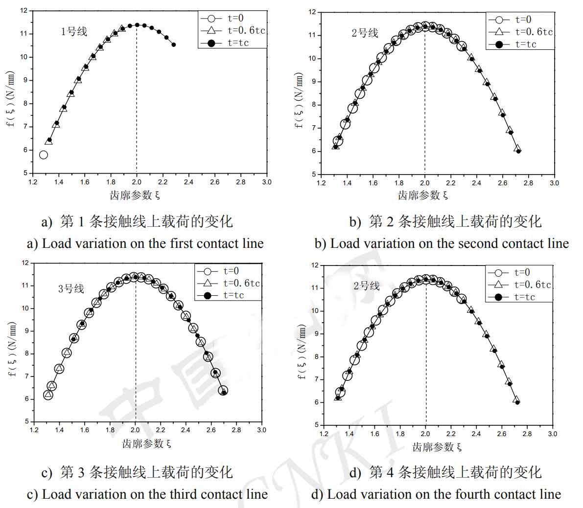
The load distribution along the contact line is affected by the position and length of the helical gear contact line. Figure 1 shows that three times are selected in an end face pitch cycle TC, and the position and length of the contact line at each time can be clearly determined, so as to clearly analyze the load distribution change law on the contact line. Where (a) is that the first contact line just enters into engagement, and the length of the first contact line is 0; (b) It is the middle time when the first contact line runs to an end face pitch cycle; (c) It refers to the position when the first contact line runs to the end of an end face tooth pitch. At this time, the length of the first contact line reaches the maximum value. Use the formula to calculate the load distribution of each contact line at each time in Fig. 1, and the curve is shown in Fig. 2:
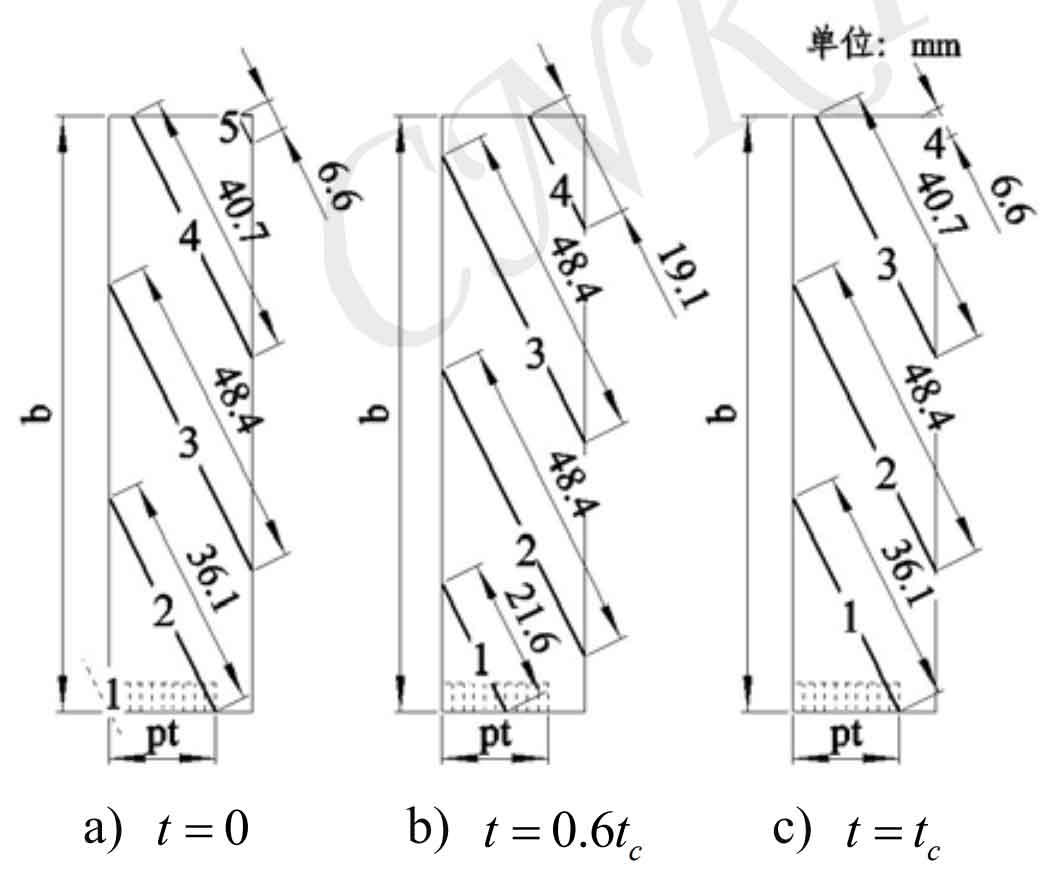
Figure 2 shows the maximum load on the node, as shown by the dotted line in the figure. In one end tooth pitch cycle, the length of the first contact line in Fig. 1 a) at the initial time is 0, which can be considered as a point of contact, so the load when the first contact line in Fig. 2 a) enters the meshing at the initial time is only a point. As the length of the contact line becomes longer, the tooth profile parameter becomes larger, and its bearing capacity becomes larger. When the contact line passes through the node, that is, when the tooth profile parameter reaches 2.04, the load reaches the maximum value. The load distribution along the contact line is affected by the position of the instantaneous meshing tooth profile and the length of the contact line.