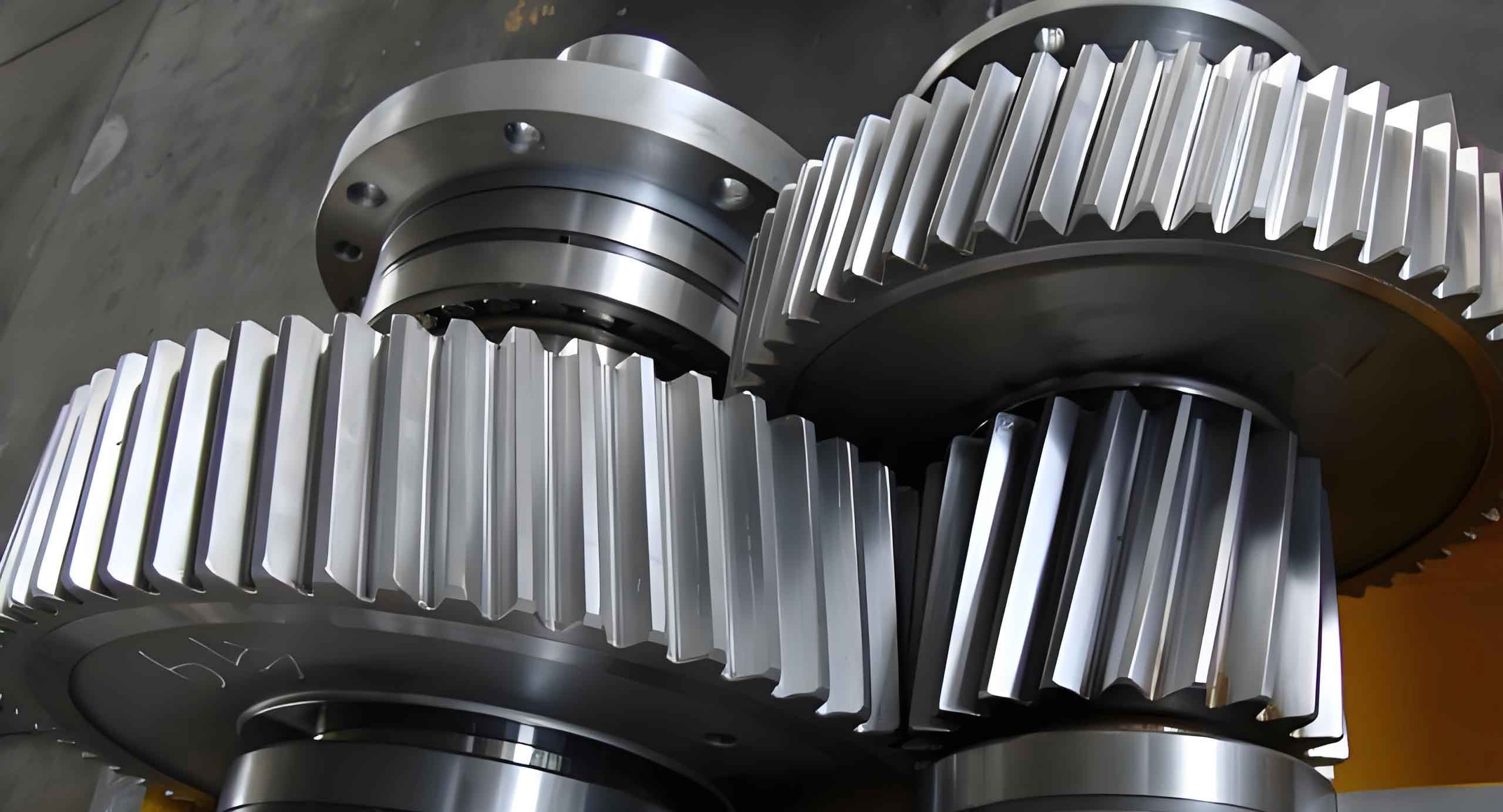
This paper investigates the dynamic friction characteristics and power transmission efficiency of helical gears through analytical modeling and parametric studies. The time-varying nature of contact lines and its influence on meshing forces are systematically explored, providing critical insights for optimizing helical gear performance in industrial applications.
1. Analytical Framework for Friction Excitation
The time-varying contact line length of helical gears fundamentally determines friction excitation. For a helical gear pair with total contact ratio $\varepsilon_\gamma = \varepsilon_\alpha + \varepsilon_\beta$, the instantaneous contact line length evolves as:
$$L(\mu) = \sum_{j=0}^{n-1} l(\mu + jp_{bt})$$
where $\mu$ represents the meshing position parameter and $p_{bt}$ denotes base pitch. The left and right segment lengths relative to the pitch line are governed by:
$$
\begin{cases}
l_L(\mu) = \dfrac{\mu}{\sin\beta_b} & \mu \leq \overline{B_2P} \\
l_R(\mu) = \dfrac{\mu – \overline{B_2P}}{\sin\beta_b} & \overline{B_2P} < \mu \leq \varepsilon_\alpha p_{bt}
\end{cases}
$$
Table 1 summarizes key geometric parameters for typical helical gear pairs:
| Parameter | Pinion | Gear |
|---|---|---|
| Number of teeth | 16 | 107 |
| Module (mm) | 5.5 | 5.5 |
| Pressure angle (°) | 20 | 20 |
| Helix angle (°) | 17 | 17 |
| Face width (mm) | 75 | 75 |
2. Time-Varying Friction Modeling
The improved EHL friction coefficient model considering surface roughness ($S$) and lubricant viscosity ($\nu_0$) is expressed as:
$$
f = e^{f(S,P_h,\nu_0)}\cdot P_h^{b_2}\left|\dfrac{S}{R}\right|^{b_3}V_e^{b_6}\nu_0^{b_7}
$$
$$
f(S,P_h,\nu_0) = b_1 + b_4|S|P_h\log_{10}\nu_0 + b_5e^{-|S|P_h\log_{10}\nu_0} + b_9e^{S}
$$
Table 2 lists the regression coefficients for mineral oils:
| Coefficient | Value |
|---|---|
| $b_1$ | -8.92 |
| $b_2$ | 1.03 |
| $b_3$ | 1.04 |
| $b_4$ | -0.35 |
| $b_5$ | 2.81 |
3. Meshing Force and Efficiency Analysis
The meshing force considering friction effects becomes:
$$
F_n(\mu) = \dfrac{T_p + T_{fp}(\mu)}{r_{bp}\cos\beta_b}
$$
Instantaneous meshing efficiency is derived as:
$$
\eta = 1 – \dfrac{1}{T_p\omega_p}|F_fV_s|
$$
Parametric studies reveal significant relationships:
- Meshing force decreases by 6-8% with surface roughness increase from 0.4μm to 1.6μm
- Average efficiency improves 0.15% per 100Nm torque increase
- Low-temperature viscosity variations (15-150cSt) cause 0.4% efficiency fluctuation
4. Geometric Optimization Insights
Optimal parameter combinations enhance helical gear performance:
$$
\begin{cases}
\text{Minimize } \Delta L = |L_{\text{max}} – L_{\text{min}}| \\
\text{Subject to: } \varepsilon_\beta \geq 1.2 \\
\beta \in [15^\circ,25^\circ] \\
b/m_n \in [10,14]
\end{cases}
$$
Key findings include:
- 17° helix angle reduces contact length variation by 38% compared to 25°
- Face width of 60mm decreases meshing force fluctuation by 29%
- Pressure angle increase from 20° to 25° improves efficiency by 0.12%
5. Dynamic Behavior Characterization
The friction-induced moment variation follows:
$$
\Delta T_f = \dfrac{\mu_0 F_n r_{bp}}{2}\left(\dfrac{\varepsilon_\alpha – 1}{\varepsilon_\gamma}\right)\sin(2\pi f_m t)
$$
Where $f_m$ represents meshing frequency. Critical observations:
- Friction torque amplitude increases 22% when $\varepsilon_\beta$ changes from 1.1 to 1.8
- Sliding velocity reversal near pitch line causes 40° phase shift in friction direction
- Multi-tooth engagement regions show 3-5× higher friction excitation than single-tooth zones
6. Industrial Application Guidelines
Practical recommendations for helical gear design:
| Parameter | Optimal Range | Efficiency Impact |
|---|---|---|
| Surface roughness Ra | 0.2-0.8μm | 0.25%/0.1μm |
| Lubricant viscosity | ISO VG 68-100 | ±0.15% |
| Helix angle | 15°-20° | 0.08%/degree |
| Face width ratio | 12-14 | 0.05%/ratio unit |
These findings provide comprehensive guidance for engineers to optimize helical gear systems in power transmission applications, particularly for high-speed and energy-efficient machinery.
