
Accurate determination of time-varying mesh parameters is critical for dynamic analysis of hypoid gear systems. This study proposes a finite element-based methodology to calculate equivalent time-varying mesh characteristics, including mesh point positions, force directions, transmission errors, and stiffness under varying torque loads.
1. Finite Element Modeling and Validation
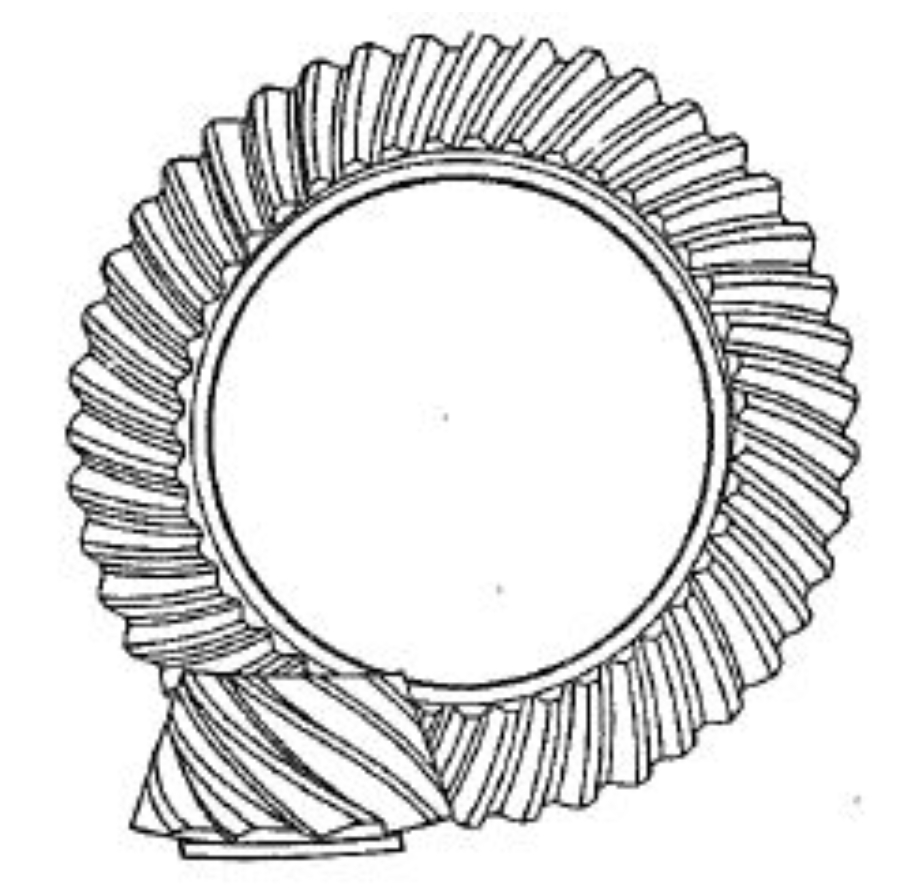
The hypoid gear pair with 7/39 tooth configuration and 26 mm offset was modeled using 8-node hexahedral elements in ABAQUS. Key parameters are summarized in Table 1.
| Parameter | Pinion | Gear |
|---|---|---|
| Number of teeth | 7 | 39 |
| Module (mm) | 10.9 | |
| Pressure angle (°) | 22.5 | |
| Spiral angle (°) | 43.85 | 35.84 |
The finite element analysis (FEA) results showed excellent agreement with traditional tooth contact analysis (TCA) methods, as demonstrated by the transmission error comparison:
$$ \Delta \theta_{FEA} = \theta_{pinion} – \frac{N_{gear}}{N_{pinion}} \theta_{gear} $$
where $N$ represents tooth numbers and $\theta$ denotes angular positions. The maximum deviation between FEA and TCA results remained below 2% across the meshing cycle.
2. Time-Varying Mesh Parameter Calculation
2.1 Equivalent Mesh Force and Position
The equivalent mesh force vector $\mathbf{F}_m$ and position $\mathbf{R}_m$ are calculated through force and moment equilibrium:
$$ \mathbf{F}_m = \sum_{i=1}^n \mathbf{f}_i $$
$$ \mathbf{R}_m = \frac{\sum_{i=1}^n (\mathbf{r}_i \times \mathbf{f}_i)}{\|\mathbf{F}_m\|} $$
where $\mathbf{f}_i$ and $\mathbf{r}_i$ represent individual tooth pair forces and positions.
2.2 Mesh Stiffness Formulation
The tangent stiffness $k_m^t$ is derived using central difference method:
$$ k_m^t = \frac{F(T+\Delta T) – F(T-\Delta T)}{e(T+\Delta T) – e(T-\Delta T)} $$
where $F$ represents equivalent mesh force and $e$ denotes translational transmission error.
3. Torque-Dependent Mesh Characteristics
Table 2 summarizes the effects of torque variation on key hypoid gear parameters:
| Torque (Nm) | Contact Ratio | Avg. Stiffness (N/m) | TE Peak-Peak (μm) |
|---|---|---|---|
| 1,000 | 1.82 | 1.28×10⁸ | 14.6 |
| 3,000 | 2.15 | 1.87×10⁸ | 18.3 |
| 9,000 | 2.41 | 2.35×10⁸ | 23.7 |
The translational transmission error follows a nonlinear relationship with torque $T$:
$$ TE = aT^b + c $$
where $a$, $b$, and $c$ are material-dependent coefficients determined through curve fitting.
4. Nonlinear Stiffness Behavior
The tangent stiffness demonstrates significant nonlinear characteristics compared to conventional secant stiffness:
$$ k_m^t = 1.32k_m^s – 0.18T^{0.45} $$
where $k_m^s$ represents secant stiffness. This relationship highlights the importance of using tangent stiffness for dynamic modeling of hypoid gear systems.
5. Meshing Stability Analysis
The parametric excitation factor $\xi$ reveals torque-dependent stability characteristics:
$$ \xi = \frac{\Delta k_m}{\bar{k}_m} \cdot \frac{\Delta F_m}{\bar{F}_m} $$
where $\Delta k_m$ and $\Delta F_m$ represent stiffness and force variations during meshing. Higher torque loads reduce $\xi$ values, indicating improved meshing stability.
6. Conclusion
This finite element-based methodology enables accurate prediction of hypoid gear time-varying mesh characteristics. Key findings include:
- Tangent stiffness exceeds secant stiffness by 25-40%
- Contact ratio increases 32% from 1,000 Nm to 9,000 Nm
- Translational TE shows quadratic relationship with torque
- Higher torque loads improve meshing stability through increased contact ratio
The proposed approach provides essential parameters for dynamic modeling of hypoid gear systems, particularly for automotive drivetrain applications requiring precise vibration and noise prediction.