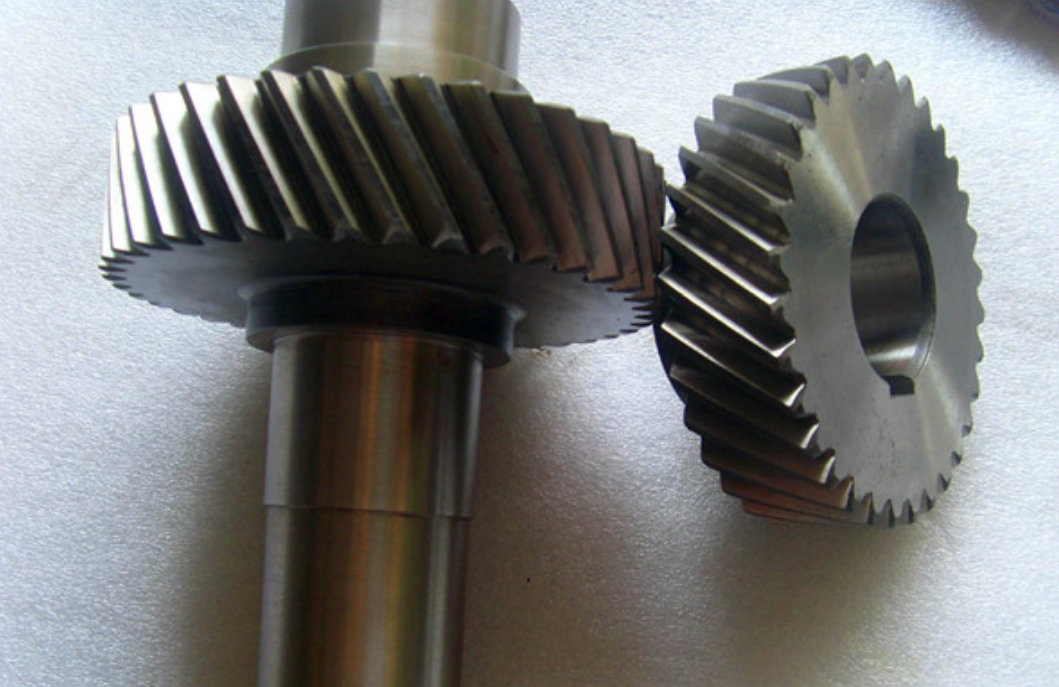
This paper presents a comprehensive study on the time-varying mesh stiffness and nonlinear dynamic characteristics of worm-helical gear transmission systems. The analytical model integrates stiffness excitation, backlash, and manufacturing errors to reveal vibration mechanisms under varying operational conditions.
1. Time-Varying Mesh Stiffness Calculation
The total mesh stiffness of helical gears consists of five components derived from elastic potential energy principles:
$$k_{total} = \left( \frac{1}{k_h} + \frac{1}{k_b} + \frac{1}{k_s} + \frac{1}{k_a} + \frac{1}{k_f} \right)^{-1}$$
Where:
$k_h$ = Hertzian contact stiffness
$k_b$ = Bending stiffness
$k_s$ = Shear stiffness
$k_a$ = Axial compressive stiffness
$k_f$ = Fillet foundation stiffness
The parametric configuration of a typical helical gear pair is shown below:

| Component | Young’s Modulus (GPa) | Poisson’s Ratio | Density (kg/m³) |
|---|---|---|---|
| Steel Worm | 209 | 0.269 | 7850 |
| PEEK Helical Gear | 3.8 | 0.40 | 1300 |
2. Dynamic Modeling of Helical Gear System
The nonlinear dynamic model considers time-varying stiffness and backlash effects:
$$m_e\ddot{x} + c(\dot{x} – \dot{e}) + k(t)f(x – e) = F_m$$
Where the backlash function $f(\delta)$ is defined as:
$$
f(\delta) =
\begin{cases}
\delta – b & \delta > b \\
0 & |\delta| \leq b \\
\delta + b & \delta < -b
\end{cases}
$$
| Parameter | Symbol | Value |
|---|---|---|
| Normal Module | $m_n$ | 0.3 mm |
| Helix Angle | $\beta$ | 15° |
| Contact Ratio | $\varepsilon$ | 1.85 |
3. Parametric Sensitivity Analysis
The dimensionless dynamic equation reveals critical relationships:
$$\ddot{\bar{x}} + 2\zeta\omega_n\dot{\bar{x}} + \omega_n^2[1 + k_1\cos(\omega_m t)]f(\bar{x}) = \bar{F}_m + \bar{e}\omega_m^2\cos(\omega_m t)$$
Key influencing factors include:
| Backlash (μm) | Vibration Amplitude | Dominant Frequency |
|---|---|---|
| 5 | 0.12 mm | 1× mesh frequency |
| 20 | 0.35 mm | 2× mesh frequency |
| 50 | 0.81 mm | Chaotic spectrum |
4. Load Distribution Characteristics
The dynamic load sharing ratio for helical gears can be expressed as:
$$LSR = \frac{F_{max}}{F_{avg}} = 1 + \frac{\Delta k}{2k_m}\sin(\pi\varepsilon)$$
Where $\Delta k$ represents the stiffness variation during meshing cycle.
| Speed (rpm) | Dynamic Response | FFT Characteristics |
|---|---|---|
| 1,000 | Period-1 | Discrete harmonics |
| 3,500 | Period-2 | Subharmonics present |
| 5,000 | Chaotic | Continuous spectrum |
5. Vibration Mitigation Strategies
Optimal design parameters for helical gear vibration reduction:
$$\zeta_{opt} = \sqrt{\frac{k_m}{4m_e}} \cdot \frac{1}{\sqrt{1 + (\pi/\ln(CR))^2}}$$
Where $CR$ represents the compliance ratio between mesh stiffness and supporting structure.
| Damping Ratio | Response Type | Acceleration RMS |
|---|---|---|
| 0.05 | Chaotic | 15.2 m/s² |
| 0.10 | Period-2 | 8.7 m/s² |
| 0.20 | Period-1 | 4.3 m/s² |
This comprehensive analysis demonstrates that helical gear dynamics are particularly sensitive to time-varying stiffness characteristics and backlash nonlinearities. The derived models provide essential guidance for optimizing vibration performance in precision transmission systems.
