
1. Introduction
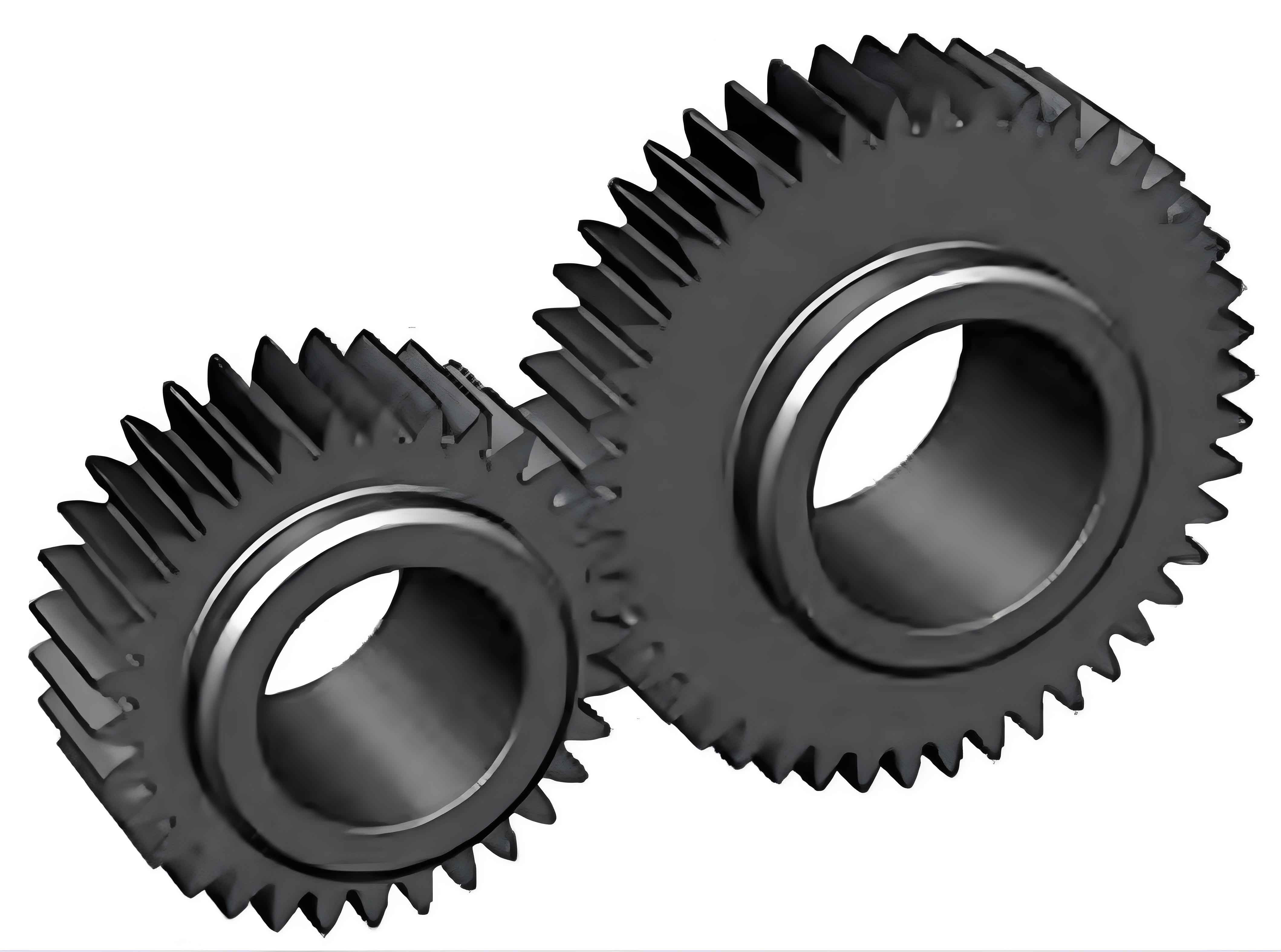
Gear-rotor systems are widely used in various industries for motion and power transmission. With the increasing demands of modern industry for spur gear transmission systems towards heavy loads, high speeds, and harsh working environments, spur gear is more prone to failures. Among gear failures, tooth root cracks account for nearly 40% of all failures. Detecting, controlling, and tracking tooth root crack failures in spur gear systems is crucial to avoid system shutdowns, economic losses, and even casualties.
The time-varying meshing stiffness can reflect various factors affecting spur gear meshing conditions. Finite Element Method (FEM) is an effective tool for calculating time-varying meshing stiffness, but it has a large computational cost and complex meshing and post-processing procedures. The energy method, on the other hand, has high computational efficiency and is currently the mainstream method for calculating time-varying meshing stiffness.
Previous studies have mainly focused on crack propagation paths and system responses at a specific crack level. There is less research on modeling fault gear teeth at different crack levels and analyzing calculation principles. In addition, the tooth root transition curve of cracked gear teeth is often approximated by an arc, and the effective tooth thickness reduction limit line is a straight line parallel to spur gear tooth centerline, which still has a certain gap from the actual situation. Moreover, the starting point of the involute tooth profile and the intersection of the involute and the base circle are not mentioned in the above literature.
This paper aims to improve the calculation formula of time-varying meshing stiffness for large tooth number gears based on the energy method, establish more accurate fault gear tooth models at different crack levels, and analyze the effects of various factors on the calculation of time-varying meshing stiffness.
2. Improved Calculation Method for Time-Varying Meshing Stiffness of Large Tooth Number Gears
2.1 Basic Principle
A plane rectangular coordinate system is established . The spur gear teeth processed by a rack-type cutter are taken as the research object. The transition curve is an equidistant line of a long-amplitude involute, and its parameter equation is given. The points G, H, and G3 represent the starting point of the involute tooth profile, the starting point of the transition curve tooth profile, and the intersection of the involute tooth profile and the base circle, respectively. The radii of the circles where these points are located are calculated as follows:
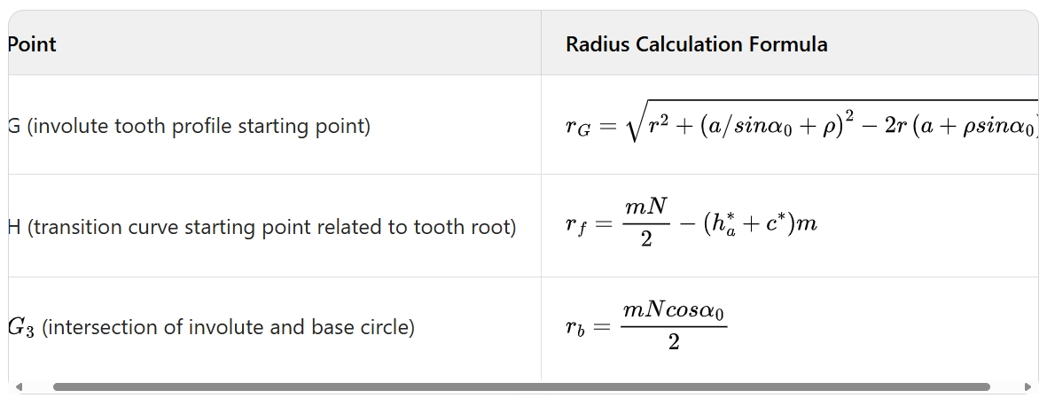
where N is the number of teeth, m is the modulus, α0 is the pressure angle, h* and c* are the tooth tip height coefficient and top clearance coefficient, respectively, and ρ is the tool tip fillet radius.
The traditional potential energy method spur gear tooth model has some problems. It only considers the relationship between the base circle τb and the tooth root circle τf and takes the intersection of the involute tooth profile and the base circle Gb as the starting point of the involute tooth profile, ignoring the fact that G and Gb are not the same point. Moreover, when the number of teeth is large, the base circle is actually located inside the tooth root circle, but the traditional model assumes otherwise.
2.2 Improved Algorithm for Time-Varying Meshing Stiffness
The total potential energy of a meshing spur gear pair consists of five components: contact stiffness ks, bending stiffness kb, shear stiffness ks, axial compression stiffness , and tooth base stiffness . The calculation formulas for Kb and Kf are given.
The deformation energy related to bending and shear can be calculated by integrating the relevant expressions. When the number of meshing spur gear teeth is not greater than a certain value, the expressions for (related to the position of points on the tooth profile) are different from those when the number of teeth is greater than that value.
Finally, the comprehensive time-varying meshing stiffness of spur gear is calculated as the sum of the reciprocals of the stiffness components of the active and passive gears.
3. Calculation of Meshing Stiffness of Large Tooth Number Cracked Gears
3.1 Calculation Models for Different Crack Degrees
It is assumed that the crack appears at point H, penetrates the entire tooth, and has an angle with spur gear tooth centerline. The crack model can be divided into four cases according to the crack expansion degree:
3.2 Further Correction of the Effective Tooth Thickness Reduction Limit Line
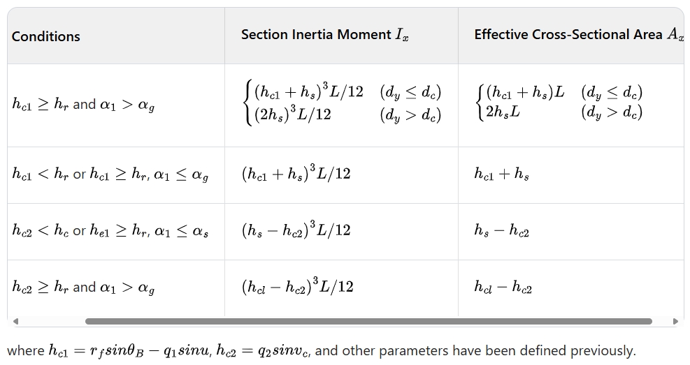
The existence of a tooth root crack reduces the effective tooth thickness. The traditional assumption of a straight line parallel to spur gear tooth centerline as the effective tooth thickness reduction limit line may lead to large errors when the crack exceeds a certain percentage of the tooth thickness. A parabolic line has been proposed as an alternative, but it has problems such as difficult modeling and complex calculations. In this paper, a 斜线连接裂纹尖端点 A 和裂纹侧齿点 K is used as the effective tooth thickness reduction limit line. When the crack is above spur gear tooth centerline and when it is below the centerline, the expressions for calculating the relevant parameters such as the section inertia moment and effective cross-sectional area are given.
4. Results and Analysis of Spur Gear Meshing Stiffness Calculation
4.1 Influence of Spur Gear Tooth Model Correction on Meshing Stiffness Calculation
The crack level (CL) is used to describe the crack expansion degree. Four crack levels are selected: A(0%), B(20%), C(40%), and D(60%). Two methods for calculating meshing stiffness are defined: one with an uncorrected spur gear tooth model and a straight effective tooth thickness reduction limit line, and the other with a corrected model and a straight limit line.
The results show that the method with the uncorrected model has a smaller meshing stiffness calculation result. This is because the uncorrected model confuses the starting point of the involute tooth profile and the intersection of the involute and the base circle, resulting in an overestimation of the deformation energy and an underestimation of the meshing stiffness. As the crack level increases, the meshing stiffness reduction percentage of both methods and the finite element method increases. In the double-tooth meshing area, the stiffness reduction amplitude in the latter meshing cycle is greater than that in the former meshing cycle.
4.2 Influence of the Effective Tooth Thickness Reduction Limit Line on Meshing Stiffness
Three methods are defined to analyze the influence of the effective tooth thickness reduction limit line on meshing stiffness: one with a straight line, one with a parabolic line, and the method in this paper with a bias. The results show that when the crack level is low (, ), the three methods have similar time-varying meshing stiffness curves and relatively small errors compared to the finite element method. When the crack level is high (), using a straight line as the limit line results in a large error, while using a 斜线 or a parabolic line is more reasonable. Considering the simplicity of modeling and calculation efficiency, the bias is more practical.
5. Conclusions
- For spur gears with more than 41 teeth, by combining the geometry of cutting teeth and the principle of tooth profile enveloping, the differences between the starting point of the involute tooth profile and the intersection of the involute and the base circle are clarified. The tooth root transition parameter curve and a more realistic effective tooth thickness reduction limit line are introduced, improving the traditional potential energy method formula for calculating the time-varying meshing stiffness of gear teeth and establishing a more accurate calculation model for the time-varying meshing stiffness of fault gear teeth at different crack levels.
- Based on the improved crack gear tooth model, the time-varying meshing stiffness at different crack levels is calculated. The results show that when calculating the time-varying meshing stiffness of large tooth number gears, not correcting spur gear tooth model will lead to a smaller calculation result. Tooth root cracks will reduce the meshing stiffness, and the reduction amplitude is greater in the second meshing cycle. As the crack degree increases, the reduction amplitude of the meshing stiffness also increases.
- When the crack size is small, the specific form of the effective tooth thickness reduction limit line has a small impact on the calculation of the time-varying meshing stiffness. It is recommended to use a straight line as the limit line. When the crack size is large, a straight line type reduction limit line does not conform to the actual situation of the crack. Compared to a parabolic line, bias can meet the calculation accuracy requirements to a certain extent, and it has simple modeling and convenient calculation, with stronger practicality. It is recommended to use a bias as the effective tooth thickness reduction limit line.