The previous gear meshing model is based on empirical design formula or gear geometric meshing analysis. With the improvement of gear design and analysis, higher requirements are put forward for gear contact analysis, so it is necessary to conduct more in-depth research on gear contact. Based on the finite element method, the meshing model of hypoid gear is established to simulate the real operation process of gear. The basic principle of gear meshing stiffness calculation is introduced in detail below.
As shown in Figure 1, the gear meshing coupling model based on the finite element model is established. From the meshing diagram, it can be seen that there are many interaction points between large and small gears at any meshing time. Each interaction point includes the influence of tooth side clearance and friction nonlinear factors. The model does not need more assumptions and constraints, and can accurately simulate the contact of gears.
In order to establish the geometric position relationship of the meshing gear in the gear meshing process, the coordinate system shown in Figure 2 is established. The coordinate systems S1 and S2 are fixed on the pinion and big gear respectively, and S0 is the global coordinate system, which coincides with the coordinate system S2. The coordinate origin of the coordinate system S1 is located at the intersection of the pinion axis and the big gear axis. The X (1) 1 axis coincides with the pinion axis and points from the small end of the pinion to the big end. The X (1) 2 axis is parallel to the axis of the big gear, also from the small end of the big gear to the big end. The X (1) 3 axis is determined by the right-hand rule. The big gear coordinate system S2 is defined in the same way.
In order to obtain the meshing stiffness, the following parameters are defined:
The contact area of the gear is discretized into smaller mesh elements. The meshing stiffness Kij is a function of the spatial shape, meshing position and applied torque of the gear
Let wt = KT δ t. Then:
Where: ntooth is the number of gears in contact at the same time; Npoint is the number of discrete elements on each contact gear pair; N (L) ij is the normal vector corresponding to each contact element; N (L) t is the equivalent normal direction at the meshing time t; KT is the equivalent stiffness at time t; δ T is the equivalent deformation at time t; F (L) t is the equivalent normal force at time t, and WT is the equivalent normal force at time t.
By defining f (L) t = (FXT fYt FZT), we can get:
Defines the position of the equivalent meshing point.
Where: R (L) ij is the position vector at any meshing point.
Acting torque of equivalent meshing position at any time:
definition λ ( l)t = r( l)t × N (L) t is the direction rotation radius, then M (L) t= λ (L) t WT, i.e.:
Available λ ( l)t = ( λ ( l)xt λ ( l)yt λ ( l)zt ) , λ ( l)xt 、 λ ( l)yt 、 λ (L) ZT is the equivalent radius of rotation around the X, y and Z axes respectively.
For an ideal rigid gear pair, the position of the driven gear can be obtained by dividing the position of the driving gear by the transmission ratio, that is:
Where: θ 2 is the rotation angle of the big gear; θ 1 is the rotation angle of the pinion; N1 is the number of pinion teeth; N2 is the number of big gear teeth.
However, since the gear pair is not always rigid, deformation will occur in the contact process, such as tooth surface bending, Hertzian contact deformation and tooth germ deformation. The difference between the actual rotation position and the theoretical rotation position of the driven gear is the transmission error:
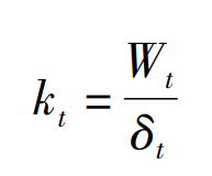
The transmission error of gear without load is Δθ 0t, transfer error after loading Δθ Lt。 Therefore, the meshing stiffness can be defined as the ratio of normal contact force to linear deformation.
Where: δ T is defined as the equivalent deformation of the meshing gear surface due to the meshing force.
Since the rotation axis of this gear is x-axis and the rotation angle around other axes is close to zero, then:
It can be obtained that the meshing stiffness at time t is:
For ideal spur gear meshing, the equivalent meshing radius λ (L) XT is a constant value, which is equal to the radius of the indexing circle. For hypoid gears, the position of the meshing point changes with the gear rotation position during gear meshing.


