
Abstract: This article focuses on the research of the tooth profile modification technology for hypoid gear processed by the forming method. It proposes to achieve the equivalent modification of the tooth profile angle by adjusting the cutter position and the installation angle of hypoid gear blank. Based on the position relationship between the cutter and the workpiece, a mathematical model for forming method processing is established. The influence of the tangential rotation of hypoid gear blank around the reference point on the workpiece axis and the machine tool center position is analyzed. The evolution relationship of processing parameters during the equivalent modification of the tooth profile angle is derived, forming a theory of equivalent modification. An example is introduced for tooth surface deviation analysis. The tooth surfaces are calculated with the processing parameters before and after the tooth profile modification, and the changing law of the tooth profile angle is compared and analyzed. Based on this, tooth surface processing and measurement experiments are carried out. The results demonstrate the feasibility of the equivalent modification theory, providing theoretical support for the forming method processing and application in enterprises.
1. Introduction
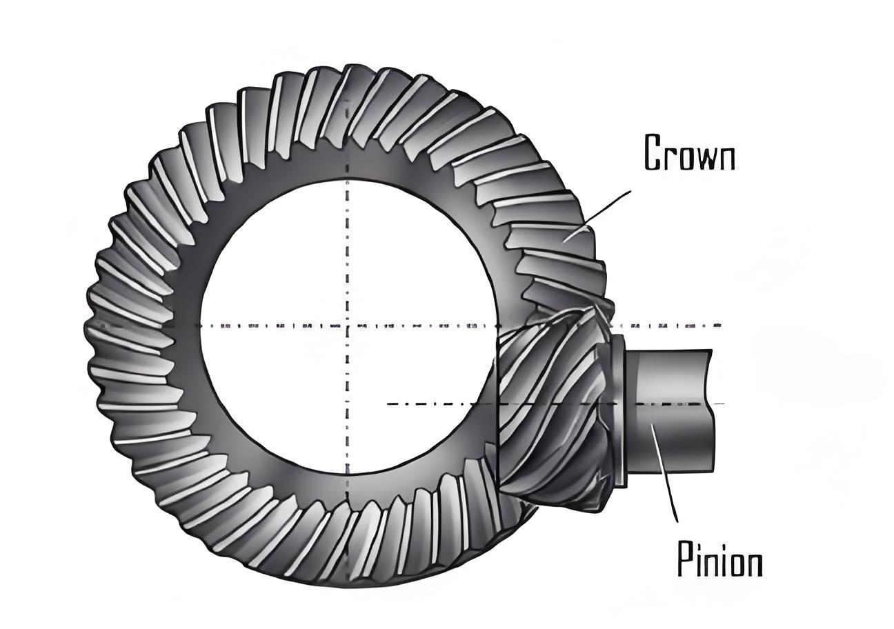
Hypoid gear is crucial components in transmission systems of automobiles, ships, engineering, and port machinery. The quality of the tooth surface formation directly affects the performance of the entire machine. The forming method has advantages such as fewer adjustment parameters and high processing efficiency, making it a main way to process the large wheel of hypoid gear. Therefore, researching the processing calculation and tooth profile modification of hypoid gear using the forming method has significant practical importance.
1.1 Related Research
Many scholars have conducted extensive research on the tooth surface processing and modification technologies of spiral bevel gear and hypoid gear. For example, Artoni et al. proposed an equivalent modification method for the processing errors of the hypoid gear pinion. Alves et al. established a five-axis CNC milling mathematical model for spiral bevel gear. Shih proposed a tooth surface modification method based on the ease-off topology. However, most of these studies are based on the generating method of spiral bevel gear, and there is limited research on the modification technology when using the forming method to process hypoid gear.
2. Tooth Profile Modification Basic Principle
2.1 Forming Method Parameters
When processing hypoid gear by the forming method, there are several parameters such as cutter position, axial wheel position, and gear blank installation angle. The hypoid gear blank is installed according to the root cone angle, and the tooth profile angle of hypoid gear is equal to that of the cutter. The cutter axis is parallel to the horizontal direction (based on a horizontal machine tool model in this study), and the root cone vertex of hypoid gear is the cutting intersection point.
2.2 Need for Modification
In the actual cutting process, due to machine tool errors, installation errors, and adjustment errors, the actual tooth profile angle of the tooth surface may not match the theoretical data, thus requiring modification of the tooth profile angle.
2.3 Modification Method
This study proposes to modify the tooth profile angle by rotating hypoid gear blank. At the cutting reference point P, hypoid gear blank is rotated around the direction. At this time, the cutter head axis is perpendicular to the machine tool plane, but there is a certain angle between the workpiece axis and the horizontal plane. This installation position of the workpiece is not achievable in actual processing and requires an equivalent conversion of the relative position. The hypoid gear blank is rotated around the cutter head axis so that the rotated workpiece axis is parallel to the horizontal plane. At this time, the installation azimuth angle of the workpiece can be achieved by adjusting the installation angle. Combined with the adjustment of the cutter position and the axial wheel position correction value, the equivalent conversion modification of the tooth profile angle of the hypoid gear processed by the forming method is completed. This method is applicable to both cases where the tooth profile angle requires fine-tuning and a large adjustment amount.
3. Forming Method Processing Mathematical Model
When the tooth profile does not need to be modified, a mathematical model for processing hypoid gear by the forming method is established.
The machine tool coordinate system, with the origin located at the machine tool center, and the plane coincides with the tool tip plane; is the cutter head coordinate system, with the origin located at the center of the cutter head tool tip plane; is the coordinate system of the reference point for calculating the tooth surface of hypoid gear, with the origin coinciding with the reference point P, coinciding with the tooth direction tangent at point P, pointing and perpendicular to the axis , and the plane parallel to the plane. is the root cone vertex of hypoid gear, coinciding with the machine tool center . is the design intersection point of hypoid gear, and are the radial cutter position and angular cutter position respectively, is the cutter head radius, is the reference point helix angle, is the workpiece installation angle, is the distance from the design intersection point to the root cone vertex, which is also the axial wheel position correction value; is the generating wheel cone distance, is the workpiece axis, and is the tooth root height.
The cutting edge of the cutter is represented in the cutter coordinate system as , and the vector equation of the generating wheel can be obtained as: where is the transformation matrix from the cutter head coordinate system to the machine tool coordinate system, and is the surface coordinates of the cutting edge of the cutter.
If the surface coordinates of the cutting edge of the cutter corresponding to point P are set as , then the generating wheel cone distance is:
The vector from the reference point P to the root cone vertex in the reference point coordinate system can be represented as:
The workpiece axis points in the direction of the installation base plane and can be represented in the reference point coordinate system as:
4. Tooth Profile Angle Modification
When the required tooth profile angles of the cutter and the workpiece are not equal or the tooth profile angle needs to be adjusted, the equivalent modification method described in this study can be used to modify the tooth profile angle of the workpiece.
4.1 Rotation of Gear Blank
If the difference between the tooth profile angles of the cutter and the workpiece is set as , the hypoid gear blank is rotated around the axis by . At this time, the root cone vertex is located behind the machine tool plane. The vector from the rotated reference point P to the root cone vertex in the reference point coordinate system can be represented as: where is a 3-order matrix for rotating the coordinate system around .
The rotated workpiece axis pointing in the direction of the installation base plane can be represented in the reference point coordinate system as:
The cutter axis in the reference point coordinate system is represented as , and the angle between the rotated workpiece axis and the machine tool plane is: This angle is the equivalent modified gear blank installation angle.
4.2 Calculation of Related Parameters
If the unit vectors in a set direction are represented as and are represented in the reference point coordinate system as: and since is perpendicular to , then , from which can be obtained.
If is represented in the machine tool coordinate system , it can be obtained as:
The angle required to rotate hypoid gear blank axis to be parallel to the horizontal plane is: Therefore, the angular cutter position is:
In the reference point coordinate system , the vector from the reference point P to the cutter head center can be represented as: \left.\vec{P O_{r}}=\left[\begin{array}{lll}0 & r_{c} & h_{r}\end{array}\right]^{T}
There are certain vector relationships as follows: where , are the components in the reference point coordinate system . Then in the reference point coordinate system is represented as: The modulus of the vector is: This value is the equivalent modified radial cutter position. The modulus of the vector is: This value is the equivalent modified axial wheel position correction value.
Combining the installation angle, angular cutter position, radial cutter position, and axial wheel position correction value calculated as above, the equivalent modification of the tooth profile angle of the hypoid gear processed by the forming method can be completed.
5. Example Analysis
5.1 Gear Parameters
To verify the correctness of the equivalent modification method of the tooth profile angle, a pair of hypoid gear is taken as an example. The geometric parameters of hypoid gear pair are shown in Table 1.
| Parameter Name | Pinion | Gear |
|---|---|---|
| Number of Teeth | 6 | 37 |
| End Face Module | 11.732 | |
| Shaft Angle /(°) | 90 | |
| Offset Distance /mm | 35 | |
| Outer Diameter /mm | 113.39 | 434.8 |
| Reference Point Helix Angle /(°) | 45L | 34.4R |
| Tooth Width /mm | 67.63 | 62 |
| Pressure Angle /(°) | Gear Convex Surface Pinion Concave Surface: 22 Gear Concave Surface Pinion Convex Surface: 23 | |
| Outer End Tooth Tip Height /mm | 14.89 | 1.84 |
| Outer End Full Tooth Height /mm | 19.14 | 18.97 |
| Face Cone Angle /(°) | 14.82 | 78.93 |
| Pitch Cone Angle /(°) | 11.31 | 78.48 |
| Root Cone Angle /(°) | 10.87 | 74.93 |
| Face Cone Vertex to Intersection Point Distance /mm | 0.57 | 2.84 |
| Pitch Cone Vertex to Intersection Point Distance /mm | -7.04 | 2.69 |
| Root Cone Vertex to Intersection Point Distance /mm | -20.15 | -0.78 |
5.2 Processing Parameters
The pressure angle correction amount is set as 0.5°. The processing parameters before and after the correction are shown in Table 2.
| Parameter Name | Before Correction | After Correction |
|---|---|---|
| Cutter Head Radius/mm | 152.4 | 152.4 |
| Cutter Tip Distance /mm | 5.2 | 5.2 |
| Cutting Edge Tooth Profile Angle /(°) | 22.5 | 22.5 |
| Radial Cutter Position /mm | 163.19 | 162.48 |
| Angular Cutter Position /(°) | 50.4 | 52.27 |
| Axial Wheel Position Correction Value/mm | -0.78 | 0.18 |
| Installation Angle /(°) | 74.93 | 74.62 |
5.3 Tooth Surface Calculation and Deviation Analysis
Based on the above geometric parameters and processing parameters, a calculation program is written to complete the calculation of hypoid gear tooth surface before and after the correction, and then imported into a three-dimensional software for modeling. The three-dimensional model of the corrected gear.
The tooth surface is calculated using the processing parameters before the correction and compared with the standard theoretical tooth surface.
For the convex surface before correction, the pressure angle is greater than the theoretical pressure angle. The tooth surface deviations at the small end tooth tip, large end tooth tip, small end tooth root, and large end tooth root are 0.072521, 0.085998, -0.063957, -0.087278 mm respectively. The maximum cumulative deviation in the tooth height direction is 0.1732 mm. For the concave surface before correction, the pressure angle is less than the theoretical pressure angle. The tooth surface deviations at the small end tooth tip, large end tooth tip, small end tooth root, and large end tooth root are 0.083527, 0.075972, -0.096748, -0.059139 mm respectively. The maximum cumulative deviation in the tooth height direction is 0.1802 mm.