The tooth surface of the crown gear is composed of the tooth direction line and the double arc tooth profile in its normal section. The double circular arc standard tooth profile shown in Figure 1 is used as the normal tooth profile of the crown gear. Refer to GB/T12759-1991 for the meaning of relevant symbols.
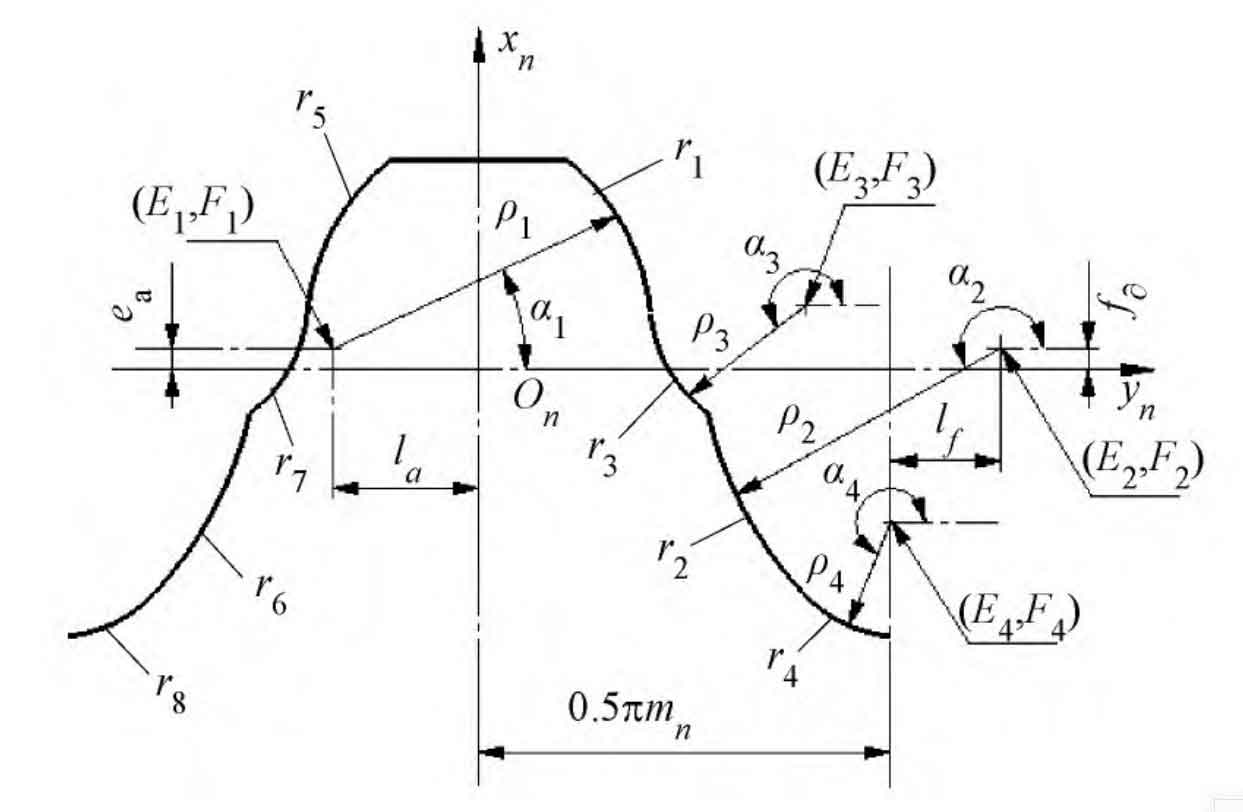
Establish the coordinate system Sn (xn, yn, zn) on the double-arc tooth profile, where the xn axis is located on the symmetry line of the tooth profile, the yn axis is located on the indexing line of the tooth profile, and the zn is perpendicular to the paper surface inward through the origin. According to the geometric relationship in Figure 1, the double-arc tooth profile equation can be expressed as:
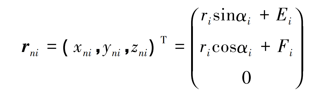
Where, ri α I, (Ei, Fi) are the radius, angle and center coordinates of each arc, i=1~8.
Because the tooth surface of the crown gear is generated by scanning the double-arc tooth profile along the actual tooth alignment line, the double-arc tooth profile coordinate system Sn is established on the actual tooth alignment line. The relationship between this coordinate system and the crown gear coordinate system Sc is shown in Figure 2.
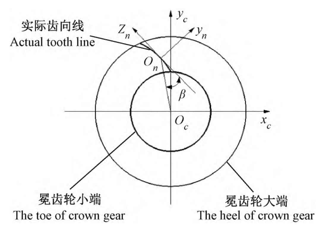
The selected helix angle is β As the tooth alignment of the crown gear, the oblique line of is, and its equation is:
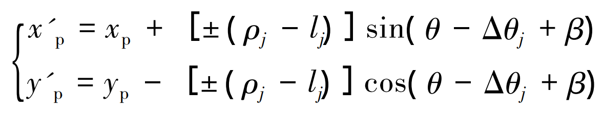
Where, ρ J and lj are the radius and center offset of the arc respectively. Where, j=1 is a convex arc, and j=2 is a concave arc; For the symbol “±”, take “-” for the left tooth profile and “+” for the right tooth profile.
According to the nutation transmission principle, combined with Figure 2 and the geometric position relationship between the gear pair, the coordinate transformation relationship between the crown gear and the inner and outer bevel gears can be established respectively, and then the tooth surface equations of the outer bevel gear and the inner bevel gear are obtained respectively: