
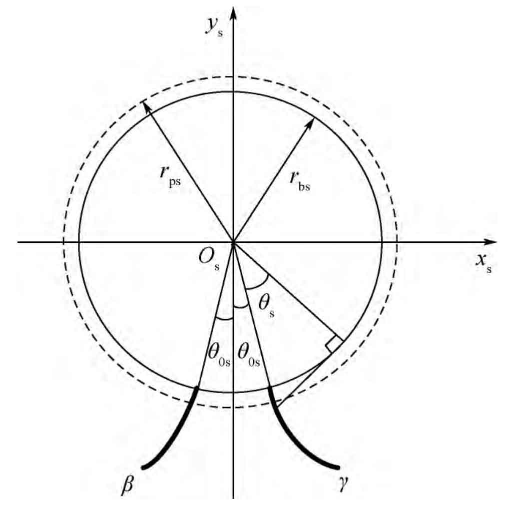
The forming of face gear tooth surface is based on the generating cutting of cylindrical spur gear shaper and face gear. The involute linear surface of face gear shaper cutter is shown in Figure 1. In the figure: RBS and RPS are involute base circle and pitch circle radius of gear shaper cutter respectively; θ 0s is the initial angle of involute of gear shaper cutter; θ S is the parameter of involute tooth surface; β And γ Represent the left and right branches of involute respectively.
The tooth surface equation of gear shaper cutter is:
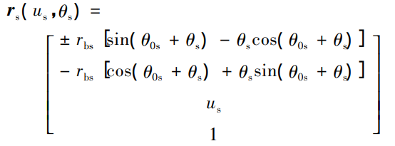
Where: RS is the involute tooth profile vector of gear shaper; Us is another parameter of involute tooth surface; “±” corresponds to involute γ、β Two.
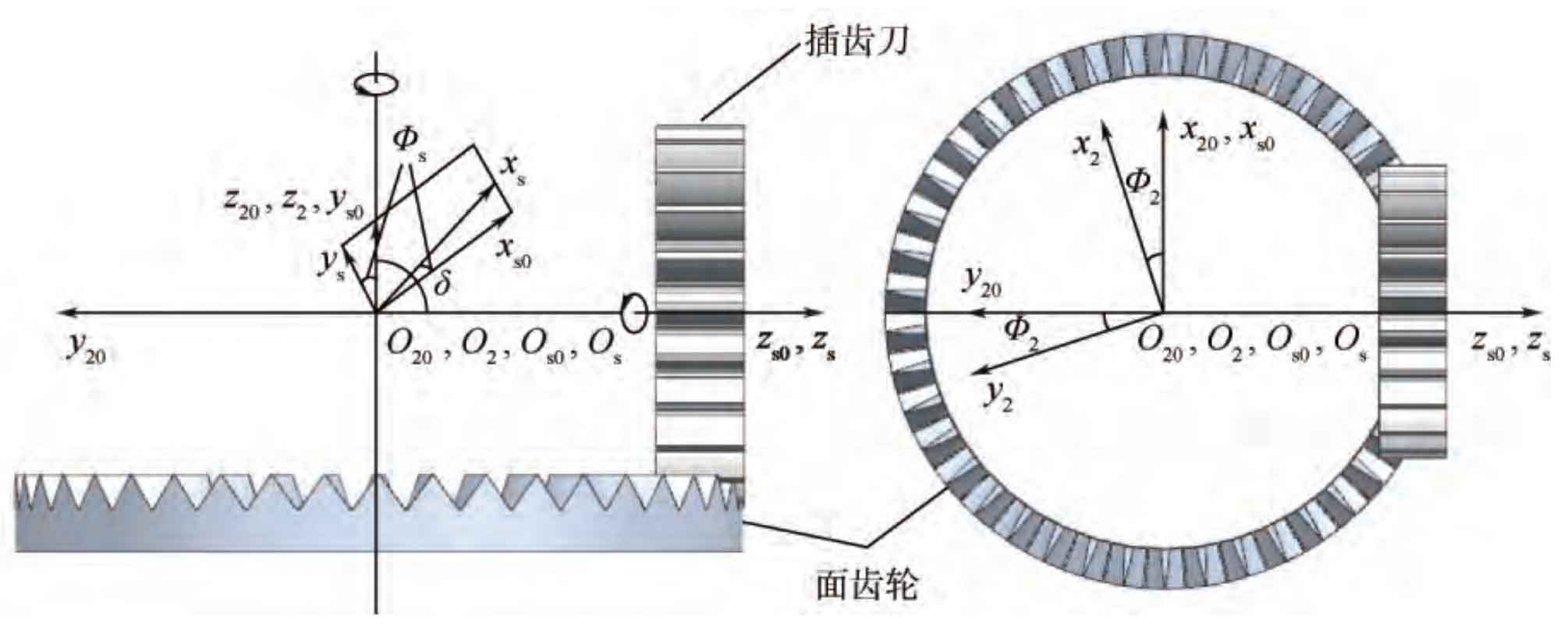
The coordinate system shown in Figure 2 can be adopted for the forming of face gear: SS (XS, ys, ZS) and S2 (X2, Y2, Z2) are the motion coordinate system fixedly connected with gear shaper cutter and face gear respectively; The fixed coordinate systems S0 (XS0, ys0, zs0) and S20 (X20, Y20, z20) are the initial positions of gear shaper cutter and face gear respectively; δ Is the shaft intersection angle, which is taken as 90 ° in orthogonal gear transmission. Rotation angle of gear shaper cutter around ZS axis Φ s. Rotation angle of face gear around Z2 axis Φ 2, and maintain the following motion proportional relationship:
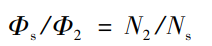
Where: N2 and ns are the number of teeth of face gear and gear shaper respectively.
The profile equation of face gear obtained by gear shaping can be obtained by coordinate transformation equation and meshing equation:
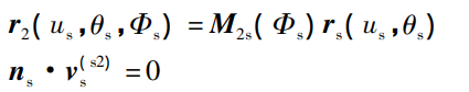
Where: M2S( Φ s) Is the conversion matrix from the coordinate system Ss to S2; NS is the normal vector of the tool tooth surface; V (S2) s is the relative velocity vector between the gear and the gear shaper cutter on the SS coordinate system.