
Take dimensionless parameter F=0.14 ε = 0. 18、 ζ = 0. 03、D = d= 1. 0、 ζ 1x = ζ 1y = ζ 1z = 0. 04、 ζ 2x = ζ 2y = ζ 2z = 0. 06、k1x =k1y = k1z = 0. 16、k2x = k2y = k2z = 0. 2、 μ d = μ k = 0. 05。 The bifurcation diagram and TLE diagram of the system in three Poincar é sections with increasing meshing frequency are obtained by numerical calculation, as shown in Figure 1. Figure 1 (a) shows the time section Γ The bifurcation diagram in n. Figure 1 (b) shows the tooth surface meshing section of straight bevel gear Γ P (x · n ≥ 0) and tooth back contact section Γ The bifurcation diagram in k (x · n<0), and Figure 1 (c) is the TLE diagram of the time section. When TLE<0, the system motion is periodic, when TLE>0, the system motion is chaotic, and when TLE=0 or jump occurs, the system has a bifurcation point.
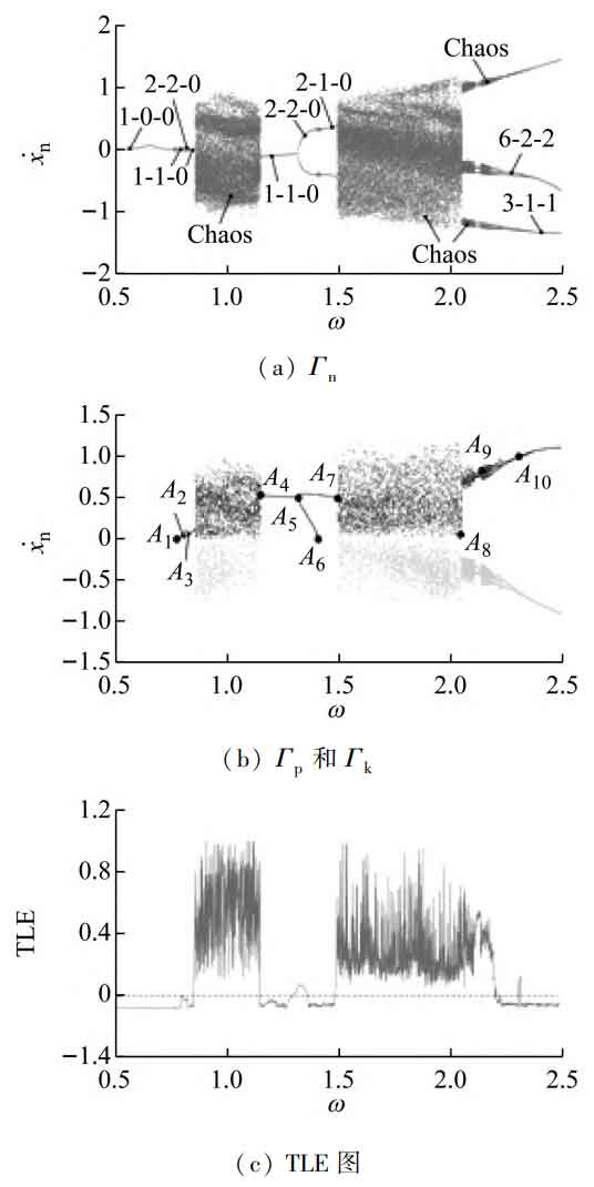
When ω When it is small, the system is in 1 ⁃ 0 ⁃ 0 motion, and the straight bevel gear is in full tooth surface meshing state, without gear tooth disengagement and tooth back contact. When ω Increase to ω = At 0.73 (A1), the system phase path is tangent to x=D, and the phase diagram and time history diagram are shown in Figures 2 (a) and 2 (b). When ω When it is increased to the right of A1 point, the system is in 1 ⁃ 1 ⁃ 0 motion, and the system is still in cycle 1 motion, but there is gear tooth disengagement. When ω When increasing to point A2, the 1 ⁃ 1 ⁃ 0 motion enters 2 ⁃ 2 ⁃ 0 motion through the doubling bifurcation, and the system phase track crosses the boundary of the tooth side gap twice, at this time, the corresponding TLE value is close to 0.
When ω When increasing to A3 point, the 2 ⁃ 2 ⁃ 0 motion degenerates into 1 ⁃ 1 ⁃ 0 motion through inverse doubling bifurcation, and its corresponding TLE value is approximately 0, and then enters chaotic motion through saddle knot bifurcation. At this time, there are three operating states of straight bevel gear tooth surface meshing, tooth tooth disengagement and tooth back contact in the system, and its Poincar é mapping diagram and time history diagram are shown in Figure 2 (c) and 2 (d). When ω When increasing to A4 point, the system degenerates from chaotic motion to 1 ⁃ 1 ⁃ 0 motion through saddle node bifurcation, and the tooth back contact in the system disappears. When ω When increasing to A5 point, the 1 ⁃ 1 ⁃ 0 motion is doubled to 2 ⁃ 2 ⁃ 0 motion. At this time, there are two motion states in the system: straight bevel gear tooth surface meshing and gear tooth disengagement. When ω When increasing to A6 point, the system phase trajectory is tangent to x=D, and the 2 ⁃ 2 ⁃ 0 motion transits to 2 ⁃ 1 ⁃ 0 motion through the friction bifurcation. At this time, the phase diagram and time history diagram are shown in Figure 2 (e) and 2 (f).
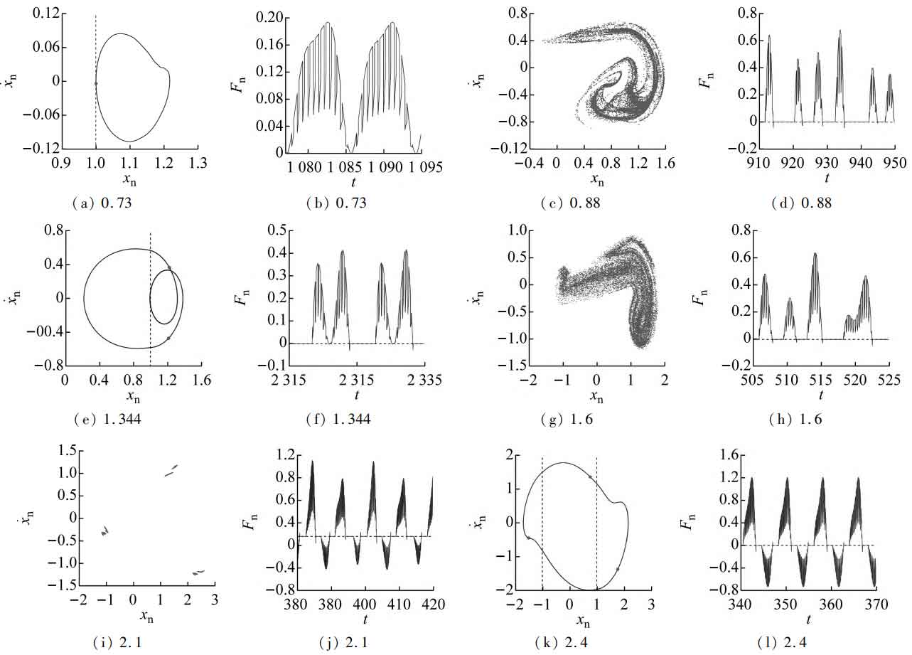
The 2 ⁃ 1 ⁃ 0 motion enters chaotic motion through saddle knot bifurcation at A7 point, and its corresponding TLE is greater than 0. At this time, Poincar é map and time history are shown in Fig. 2 (g) and 2 (h). The chaotic region system has three operating states: straight bevel gear tooth surface meshing, gear tooth disengagement and tooth back contact. With ω As a result, the A8~A9 point system has a new chaotic movement, and its topological structure is different from that before. At this time, the Poincar é map and time history are shown in Figures 2 (i) and 2 (j).
When ω > 2.2 (to the right of point A9), the system degenerates from chaotic motion to 6 ⁃ 2 ⁃ 2 motion after inverse doubling bifurcation sequence. When the meshing frequency increases to A10 point, 6 ⁃ 2 ⁃ 2 motion is inversely multiplied to 3 ⁃ 1 ⁃ 1 motion, and its corresponding TLE value changes abruptly. At this time, Poincar é map and time history map are shown in Fig. 2 (k) and 2 (l) respectively.
It can be seen that when the meshing frequency is small, the system is in a stable meshing state of straight bevel gear tooth surface. With the increase of the meshing frequency, the system gradually appears gear tooth disengagement, and its motion type also changes from stable periodic 1 motion to complex multi-period motion. The system behaves as chaotic motion near the 1st and 1.5th octave frequencies, and the system presents a tooth back contact state in the chaotic motion region. After the 2.2 octave frequencies, the system reappears multi-period motion, but the tooth back contact state still exists. With the increase of meshing frequency, the multi-state meshing behavior and motion characteristics of the system become more complex, and the desired motion characteristics can be obtained by selecting a reasonable meshing frequency.