
The gear tooth surface obtained by virtual machining and the gear tooth surface actually processed by the machine tool are composed of multiple micro segment surfaces. The more micro segment surfaces, the smoother the tooth surface tends to be. In theory, only when the cutting time interval between each two times tends to be 0, the obtained tooth surface can be smooth. The tooth surface composed of multiple micro curved surfaces with discontinuous curvature will bring difficulties to the subsequent finite element analysis. After reconstructing the micro segment surface of the tooth groove into a smooth tooth groove surface, the geometric model of spiral bevel gear is obtained, which is convenient for finite element analysis.
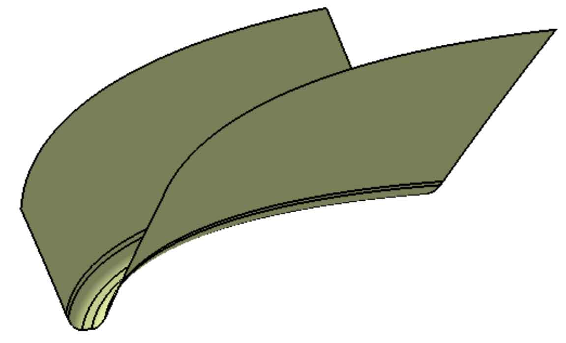
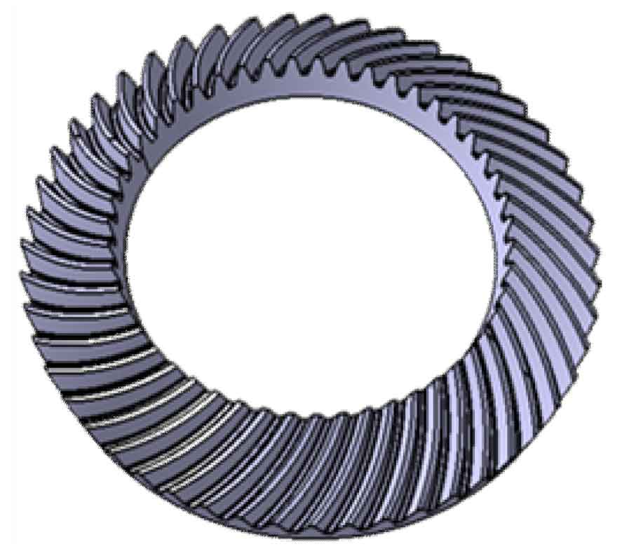
After obtaining the cut cogging model, taking the endpoint of the cutting trace line as the sampling point, the reference line is fitted with second-order continuous bicubic non-uniform rational B-spline (NURBS) to obtain a smooth fitting curve. Taking the fitting curve as the guide line and the cutting trace as the contour line, the cogging surface with uniform curvature is reconstructed. Figure 1 shows the cogging reconstruction surface of large spiral bevel gear. An accurate geometric model of spiral bevel gear can be constructed after cutting and array operations in the gear blank, as shown in Figure 2.
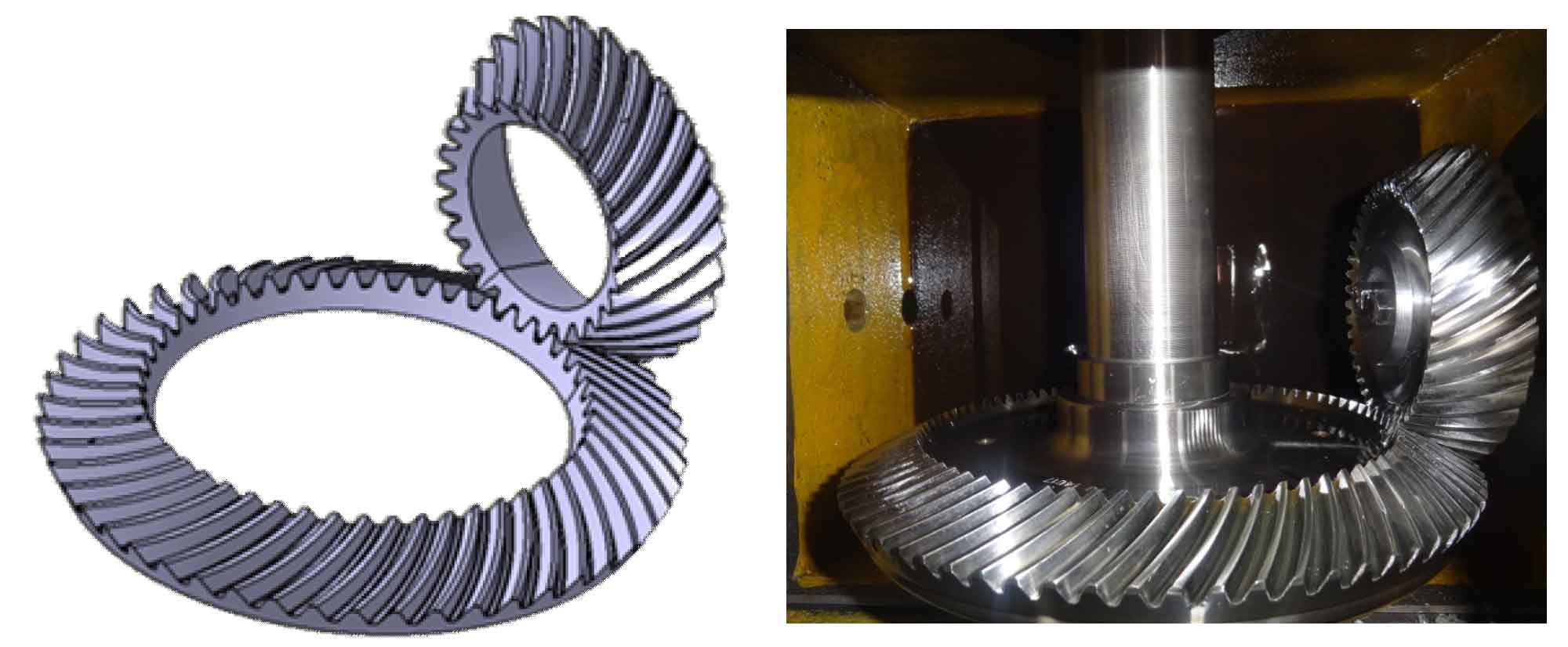
The steps of creating the geometric model of spiral bevel gear and pinion are basically the same as the above steps. Only in the process of creating the pinion, the convex and concave surfaces of the pinion are generated separately, and the relative positions of the two are determined according to the meshing position with the big wheel. Figure 3 shows the geometric model of spiral bevel gear after assembly and the gear solid assembly drawing with the same parameters.