
The torsional vibration analysis model only considers the torsional vibration of the system. In the vibration analysis of the gear system, if it is not necessary to consider the transverse and axial elastic deformation of the transmission shaft and the elastic deformation of the support system, the system can be simplified into a pure torsional vibration system. This is the case for the driving and driven bevel gears of aeroengines.
Without considering the elastic deformation of transmission shaft, bevel gear support shaft and bevel gear box, the bevel gear transmission system can be simplified into the torsional vibration model of gear pair. The torsional vibration analysis model of a typical pair of bevel gear transmission is shown in the figure:
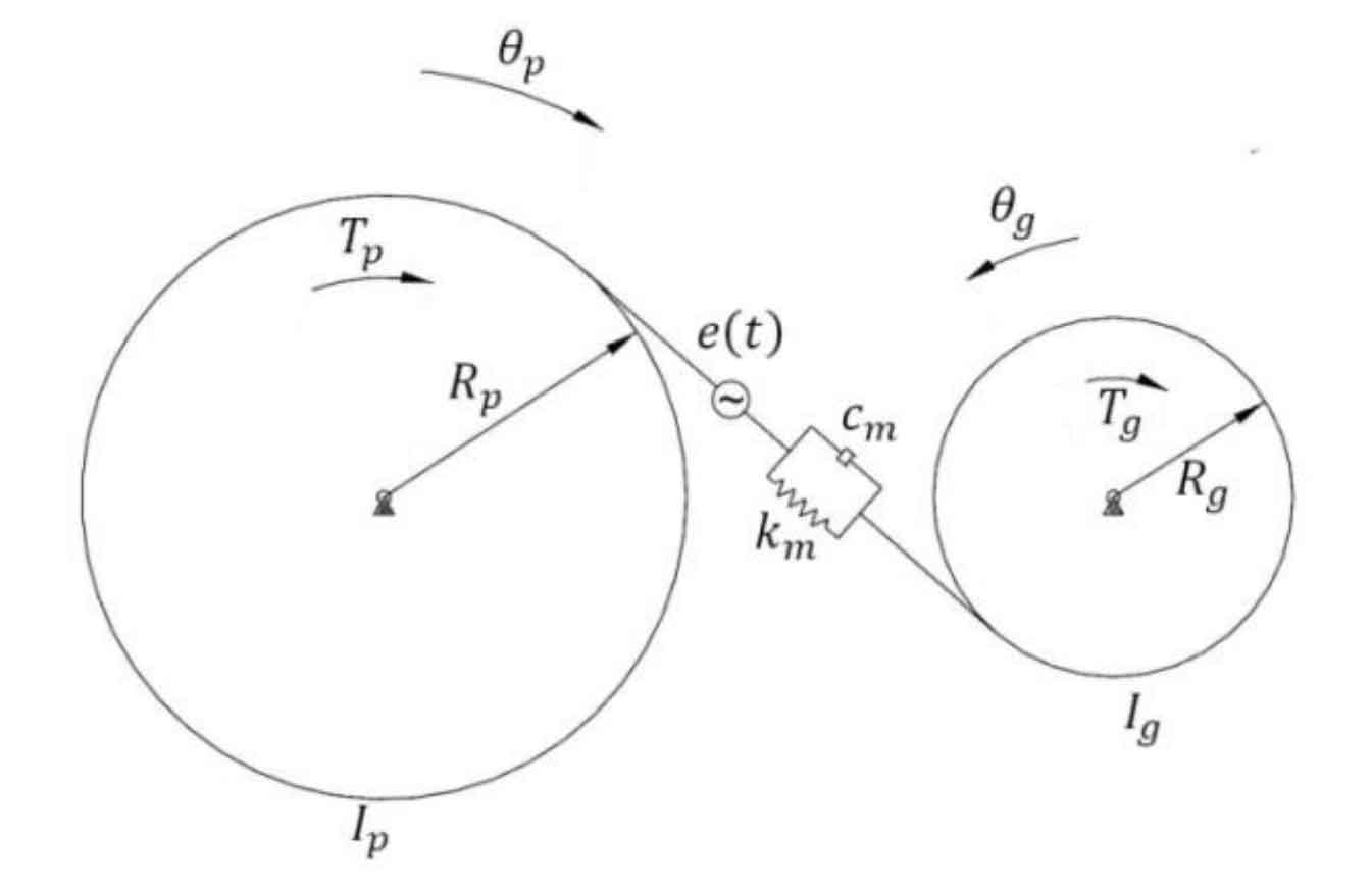
The torsional vibration analysis model of a pair of bevel gear transmission can be deduced from the figure:
When considering the dynamic model of bevel gear transmission system, based on a pair of pure torsional vibration analysis models of bevel gear transmission, considering the central transmission rod connected with the driven bevel gear, the transmission shaft connected with the driving bevel gear, prime mover and load, the torsional vibration problem of bevel gear transmission system is formed. Its dynamic model is shown in Figure 2:
For the vibration system shown in the figure, the prime mover, driving gear, driven gear and load are simplified into four elements with moment of inertia without considering the mass of the connecting shaft. Therefore, the analysis model is a torsional vibration system with four degrees of freedom, which describe the torsional vibration displacement of the four moment of inertia elements in the system θ m , θ p, θ G and θ L deduces the dynamic equation of the model as:
The dynamic meshing force WD of bevel gear teeth is:
After sorting out the above formulas, the matrix expression is:
Where:{ δ} Is the vibration displacement matrix; [m] , [C] and [k] are mass matrix, damping matrix and stiffness matrix respectively; Load column matrix.