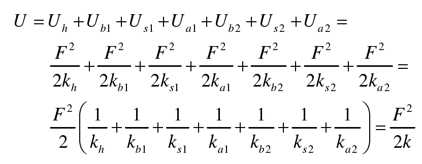
(1) When the gear teeth are in the single tooth meshing area, the total energy u in the meshing pair can be expressed as follows:

Where:
UI — energy of corresponding component, (I = h, B, s, a);
K — total meshing stiffness of gear teeth.
According to the formula:

Therefore, the total meshing stiffness K can be expressed as follows:

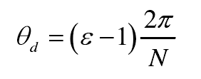
The meshing range of single tooth is as follows:

Among them:

Where:
ε – coincidence degree of gear engagement.
(2) Similarly, in the double tooth meshing area, the total meshing stiffness of teeth can be expressed as follows:

Where:
I = 1 – the first pair of meshing teeth;
I = 2 – the second pair of meshing teeth.
Double tooth meshing range:


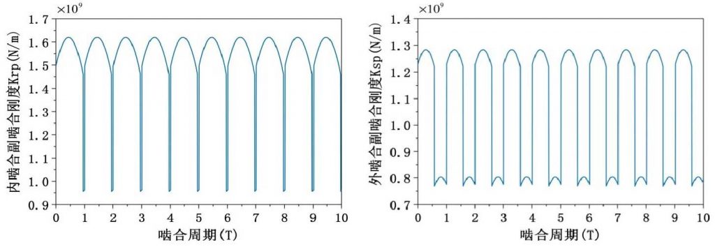
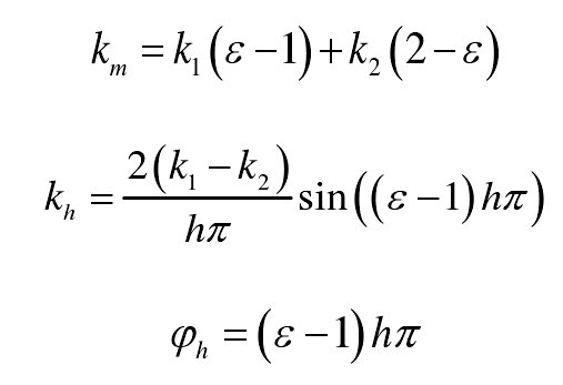
According to the above method, the time-varying meshing stiffness of the internal and external gear meshing pairs is obtained. In practical application, the time-varying meshing stiffness of gear pair will be rewritten into various forms according to the specific situation. In the process of solving the dynamic equation of gear transmission system, the meshing stiffness can also be expanded into Fourier series with meshing frequency as the fundamental frequency. The meshing stiffness of internal and external gear pairs can be expressed in the form of Fourier as follows:

Where:
Km — average value of meshing stiffness;
KH — the H-th harmonic component;
φ h — the H-th stiffness harmonic phase angle;
H — order of Fourier expansion;
Among them:

Where:
K1 — meshing stiffness of double teeth meshing;
K2 — meshing stiffness of single tooth meshing.
