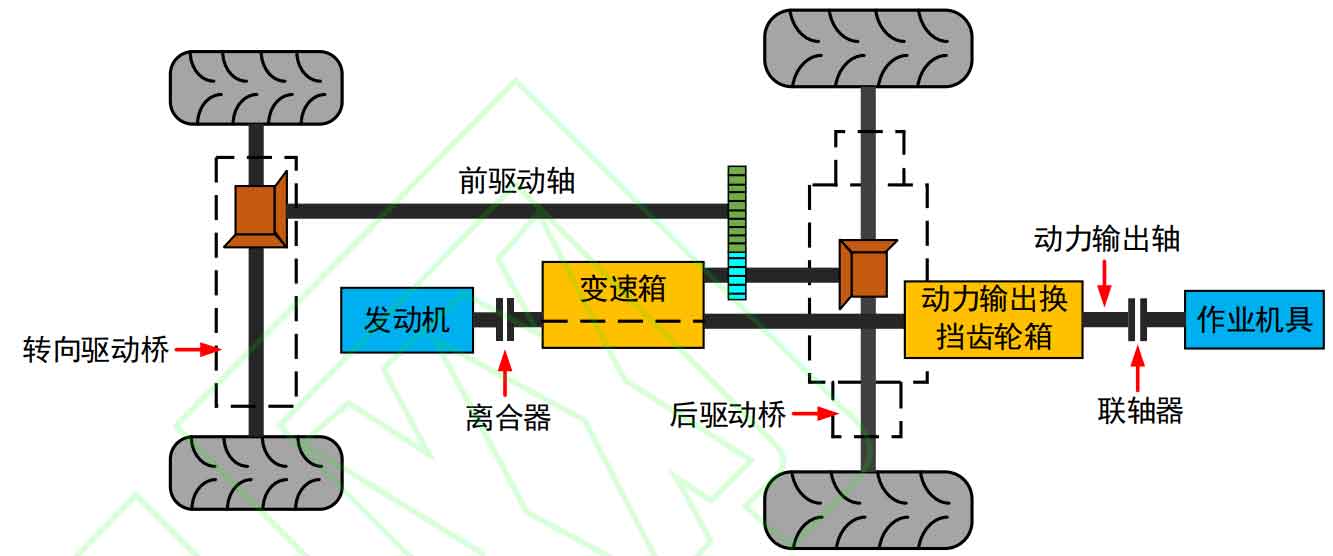
Taking LX2204 tractor as an example, the structure diagram of the transmission system of the whole machine is shown in Figure 1. In the field rotary tillage operation, part of the power output by the engine drives the wheels through the clutch, gearbox and front and rear drive axles; Most of the power is transmitted to the work tool through the PTO clutch, the PTO shift gear box, the power output shaft, and the coupling.
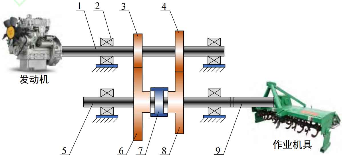
The structure diagram of the tractor power output transmission system is shown in Figure 2, mainly including the driving shaft, driving gear, driven gear, internal gear, driven shaft, PTO shaft and other parts. When the internal gear moves to the left, the power output shaft switches to the 540r/min gear; On the contrary, shift to the 1000r/min gear after moving to the right. The 1000r/min gear is generally suitable for heavy load rotary tillage of large tractors.