
According to the analysis of spiral bevel gear tooth surface machining, based on the generation principle of spherical involute tooth surface, the reverse motion of tooth surface generation motion is taken as the cutting motion, and the tooth surface of spherical involute spiral bevel gear can be milled through simple three-axis linkage. The three linkage motions are: ① the gear blank rotates around its own geometric rotation axis, and the angular velocity is ω 1; ② The blade moves with the revolution of the (q) plane, and the angular velocity is ω; ③ The blade rotates around its geometric center, and the angular velocity is ω 0 On the premise that the cutter position q is equal to the blade radius r, in order to cut the complete tooth surface of spiral bevel gear, the speed relationship of the above three must meet the formula.
Since the above three linkage motions are rotary motion, and in fact, linear motion is easier to realize and control than rotary motion, this section will further analyze and synthesize the above three linkage motions, so that the motion required for tooth surface cutting can be converted from rotary motion to linear motion as much as possible. Based on the cutting motion analysis of the tooth surface of involute spiral bevel gear, the revolution and rotation of the blade are further analyzed, as shown in the figure.
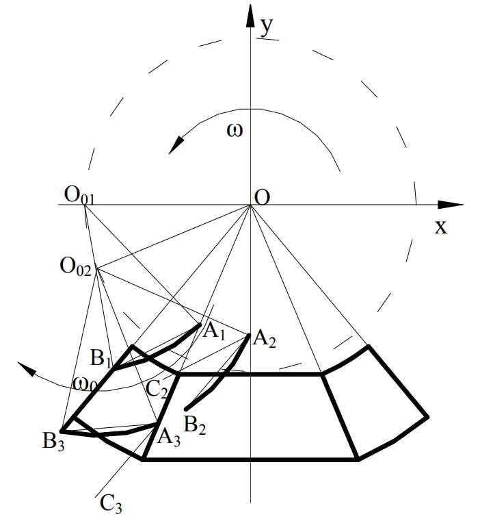
Step 1: the arc-shaped blade rotates at an angular speed around point o ω Rotate, that is, the revolution of the blade. After time t, the blade rotates from position A1B1 to a2b2, and the geometric center of the blade also rotates from o01 to O02, which is equivalent to that the whole arc blade rotates around point o ω T angle. The rotating graph has the following properties: after rotation, each point on the graph rotates the same angle in the same direction around the rotation center. The angle formed by the connecting line between any pair of corresponding points and the rotation center is the rotation angle, and the distance from the corresponding point to the rotation center is the same. It can be seen that after the figure rotates a certain angle around the rotation center, the included angle of the corresponding line segment on the figure is equal to the rotation angle. Then the included angle between the straight line segment A1B1 and the straight line a2b2 in the figure is the revolution angle of the blade in t time ω t。 Make the auxiliary line a2c2 in the figure so that a2c2 is parallel to the straight line segment A1B1. According to the nature of the parallel line, the included angle between the straight line segment a2c2 and a2b2 is also the same ω t。 The blade rotates from position A1B1 around point O to a2b2 in another way: the blade first translates so that point A1 coincides with point A2, and then the arc blade rotates counterclockwise around point a ω Tangle so that it coincides with position a2b2.
Step 2: the blade rotates clockwise around the geometric center O02 of the arc blade a2b2 within the same t time, and the angular velocity is ω 0, through the rotation angle ω After 0t, reach position a3b3. According to the method of the first step, the revolution of the blade can be realized in the following ways: the blade first translates so that the A2 point of the blade coincides with the A3 point, and then the arc blade rotates clockwise around point a ω 0t angle to coincide with position a3b3.
Synthesize the above two steps, and the blade ω Revolution at speed and ω The linkage of rotation at 0 speed can be realized equivalently in the following ways: the end point a of the arc-shaped blade is taken as the reference point, and the end point a of the blade slides along the direction of of the boundary between the cutting area and the adjustment area, while the arc-shaped blade moves in the direction of( ω 0- ω) The angular velocity of rotates around point a. According to the tooth surface cutting principle in Chapter 2, on the premise that the tool position q is equal to the blade radius r, ω 0=2 ω。 Then the angular velocity of the blade around the end point a is ω。