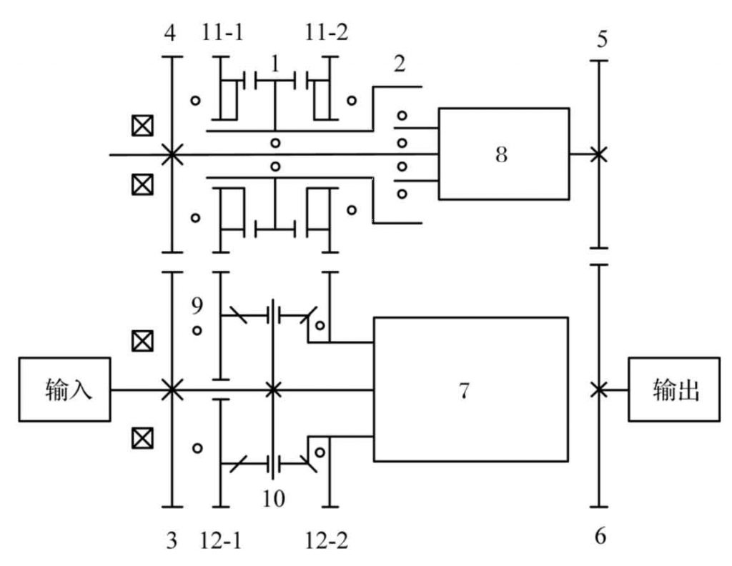
The transmission ratio of non-circular gear can be changed according to the established motion law. Compared with the connecting rod, cam and other mechanisms, it has the advantages of strong reliability, high cost performance, good dynamic characteristics and accurate transmission ratio, so it is widely used in the mechanical field. Non circular gear CVT can overcome the disadvantages of traditional steel belt CVT, which is difficult to meet the requirements of high speed and high torque. It is a CVT scheme worth exploring. However, when non-circular gear rotates at high speed, it will produce large inertial load, which will aggravate the wear of bearing and other parts, reduce the service life and increase the noise, Therefore, it is of great significance to study and optimize the static balance of non-circular gears for the development of this kind of transmission.
The non-circular gear continuously variable transmission uses two non-circular gear pairs as the two inputs of the differential. After the superposition of the differential, it outputs a fixed transmission ratio within a certain angle range. When the relative phase of non-circular gear pair is adjusted, the output constant transmission ratio also changes. Because the process of adjusting the phase is continuous, the range of output constant transmission ratio is continuous, that is, continuously variable. The structural diagram of the transmission is shown in Figure 1. In order to reduce the axial size as much as possible, AXK series thrust bearings are arranged among the bearings (bearing 9, etc.).
The reciprocal curve of transmission ratio of non-circular gear is from 〔 0 〕 °,θ] Straight line and [ θ, three hundred and sixty °] The sine (cosine) curves of are spliced together (as shown in Figure 2). This kind of alignment can avoid the sharp point of pitch curve. Let the mean value of the linear segment C = 1, the amplitude of the linear segment s = 0.34, and the span of the linear segment θ = two hundred and sixty °, The pitch curve of non-circular gear is shown in Fig. 3, and the profile of non-circular gear with backlash is shown in Fig. 4.


