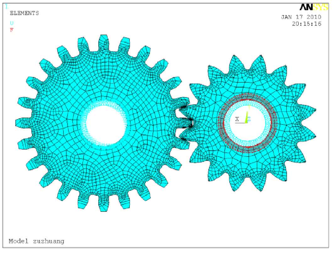
Consistent with the boundary condition setting of the smooth spur gear, restrict the degrees of freedom of all nodes in the inner hole of the big gear, restrict the degrees of freedom of all nodes in the UX direction of the inner hole of the small gear, and apply a certain torque in the uy direction. The magnitude of the torque is calculated by the previous formula, T2 = 132.18 n · M. due to the change in the number of nodes in the inner ring after meshing of the gear with concave bionic shape.
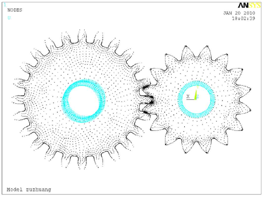
Therefore, the added gear loading torque also changes. The boundary conditions and contact loading of the gear with concave bionic shape are shown in Figures 1 and 2.
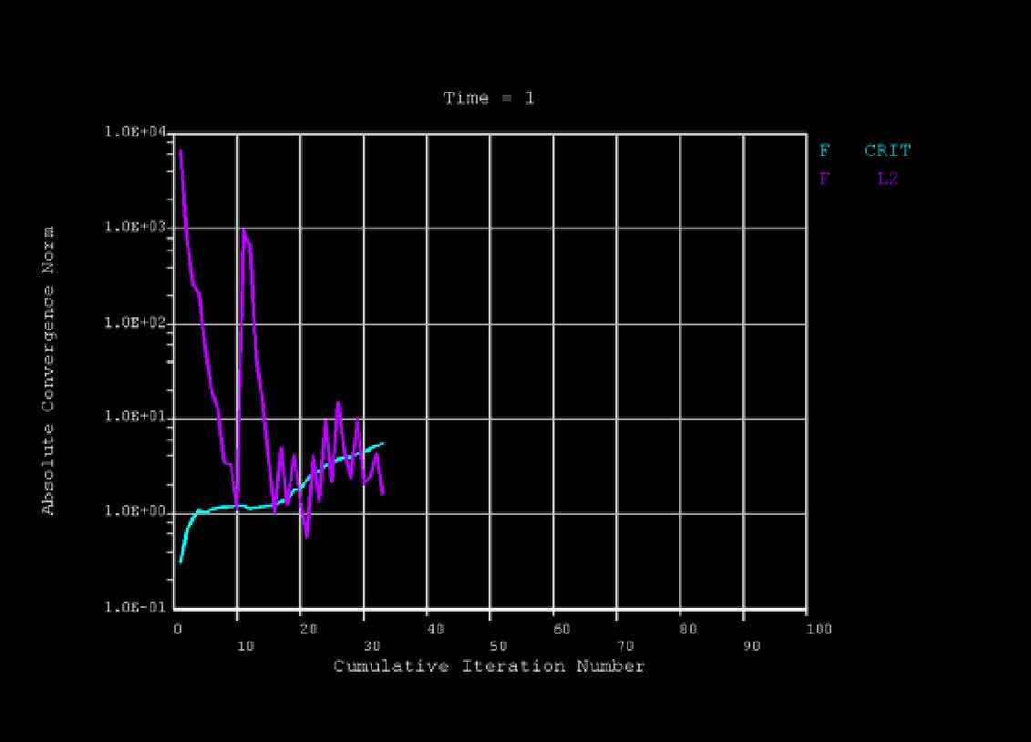
The solution setting of the contact analysis of the concave bionic gear is consistent with that of the smooth gear. The convergence curve of the nonlinear solution of the concave gear obtained after the finite element analysis is shown in Fig. 3.