
Introduction
The rapid depletion of fossil fuels and escalating environmental concerns have accelerated the development of electric vehicles (EVs). A critical component in enhancing EV performance is the electric vehicle gearbox, which optimizes motor efficiency across varying driving conditions. Traditional single-speed transmissions often force motors to operate outside their optimal efficiency range, particularly during high-speed cruising or steep climbs. This study proposes a two-stage planetary gearbox tailored for EVs, combining compact design, high energy density, and seamless gear transitions.
Structural Design of the Planetary Gearbox
Key Components and Layout
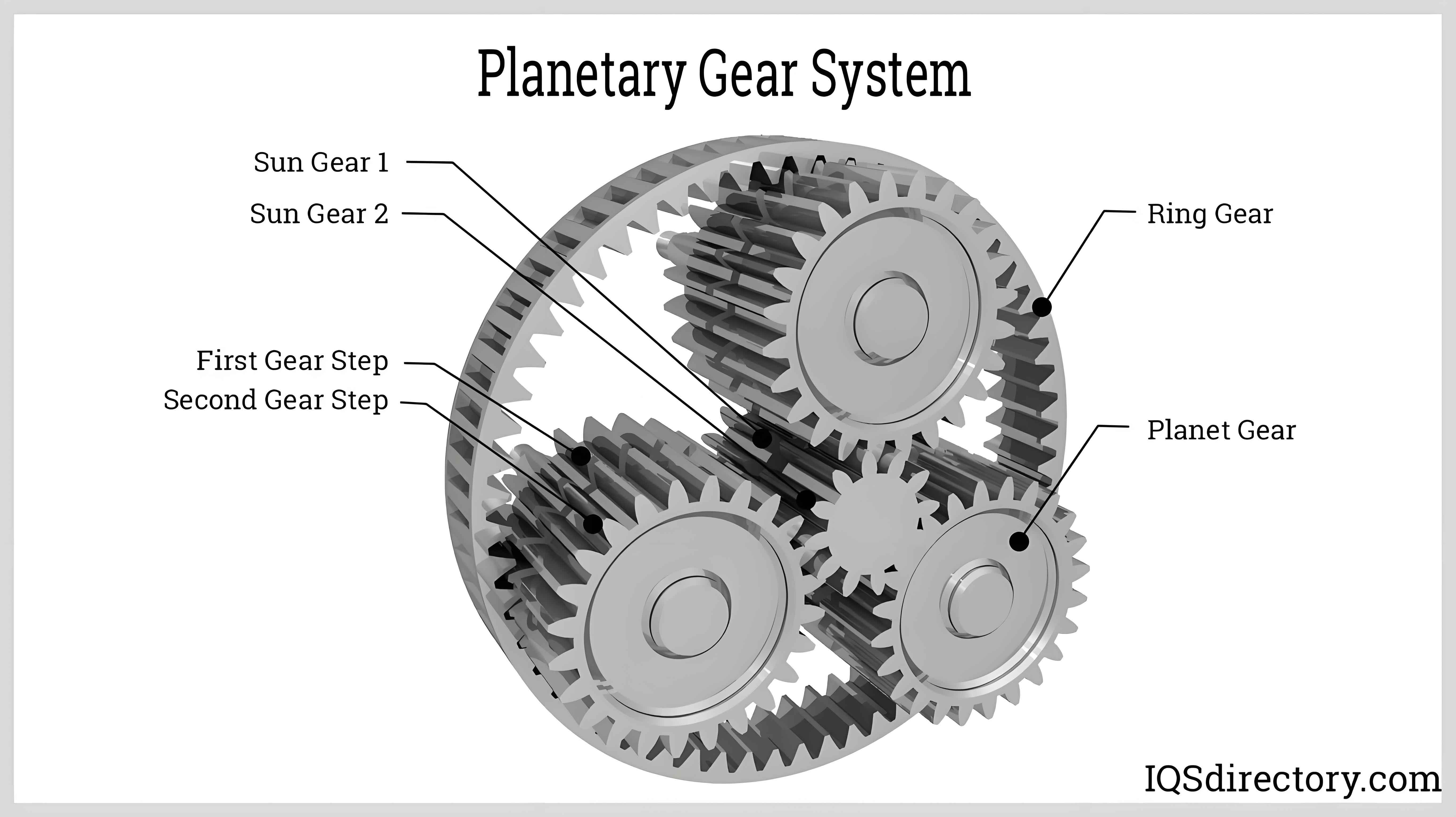
The gearbox integrates two planetary gear sets (Figure 1):
- Input Stage: Connects to the motor via an input shaft.
- Output Stage: Delivers torque to the wheels through an output shaft.
Each stage includes sun gears, planet gears, ring gears, and carriers. Braking mechanisms for the sun gear or ring gear enable two distinct gear ratios.
Gear Ratio Calculation
The gear ratios were derived using kinematic equations for planetary systems. For climbing conditions (1st gear), the ring gear is fixed, yielding:i1=R2+1R1+1=1.81(Total ratio: 10.86)i1=R1+1R2+1=1.81(Total ratio: 10.86)
For high-speed conditions (2nd gear), the sun gear is fixed:i2=(R2+1)R1(R1+1)R2=0.8(Total ratio: 4.8)i2=(R1+1)R2(R2+1)R1=0.8(Total ratio: 4.8)
Here, R1=1.7R1=1.7 and R2=4.3R2=4.3 represent the radius ratios of ring-to-sun gears.
Material Selection and Gear Parameters
Critical components were designed using 20CrMnTi (case-hardened) for sun/planet gears and 42Cr (tempered) for the ring gear. Key dimensions are summarized below:
| Component | Diameter (mm) | Teeth Count | Module (mm) |
|---|---|---|---|
| Input Sun Gear | 150 | 43 | 3.5 |
| Output Sun Gear | 66.5 | 19 | 3.5 |
| Input Planet Gear | 59.5 | 17 | 3.5 |
| Output Planet Gear | 101.5 | 29 | 3.5 |
| Ring Gear | 269.5 | 77 | 3.5 |
Static Structural Analysis
Finite Element Modeling
A 3D parametric model was developed in SOLIDWORKS (Figure 2) and imported into ANSYS Workbench for static stress analysis. Boundary conditions simulated maximum torque (250 Nm) during climbing (1st gear) and high-speed (2nd gear) scenarios.
Stress and Deformation Results
- 1st Gear: Maximum stress (524 MPa) occurred at the input sun-planet gear interface (Figure 3a). Deformation reached 0.000762 m at the carrier shaft.
- 2nd Gear: Stress peaked at 53.2 MPa on the output planet gears (Figure 3b), with negligible deformation (<1.44×10⁻⁵ m).
Both scenarios confirmed material safety margins (20CrMnTi: σlim=1400σlim=1400 MPa; 42Cr: σlim=750σlim=750 MPa).
Dynamic Simulation and Control
MATLAB/SimDriveline Model
A dynamic model (Figure 4) incorporated:
- Motor: Permanent magnet synchronous motor (75 kW, 250 Nm).
- Gearbox: Kinematic equations (Eq. 4.7–4.14) for torque/velocity transmission.
- Wheel Load: Tv=0.004ωw2Tv=0.004ωw2 to emulate road resistance.
Shift Transient Analysis
- Upshift (1st → 2nd): Motor speed dropped from 6000 RPM to 2000 RPM, while torque surged from 135 Nm to 230 Nm (Figure 5a).
- Downshift (2nd → 1st): Speed reverted to 6000 RPM, torque stabilized at 135 Nm (Figure 5b).
Transient delays (0.3 s upshift; 0.2 s downshift) validated smooth gear transitions.
Impact on Vehicle Efficiency
ADVISOR Simulation Setup
Two configurations were tested under the NEDC cycle:
- Single-Speed Gearbox: Fixed ratio = 6.
- Two-Speed Gearbox: Ratios = 10.86 (1st), 4.8 (2nd).
Results and Comparison
- Battery Current: The two-stage electric vehicle gearbox reduced peak current by 15–20% during acceleration (Figure 6a).
- State of Charge (SOC): After 1200 s, SOC improved by 7% (0.30 vs. 0.25 for single-speed) (Figure 6b).
Conclusion
- The proposed two-stage electric vehicle gearbox enhances torque delivery (230 Nm in 1st gear) and motor efficiency (2000–6000 RPM range).
- Static and dynamic simulations validated structural integrity (<524 MPa stress) and transient performance (0.3 s shift delay).
- ADVISOR results demonstrated a 7% improvement in energy economy, extending EV range.
Future Work
- Prototype Testing: Validate simulations under real-world conditions.
- Control System Optimization: Refine shift logic for adaptive driving modes.
- Multi-Objective Design: Integrate lightweight materials (e.g., carbon fiber) for further efficiency gains.