
Ultrasonic testing technology is a common method in the internal quality testing of large steel castings. Because of many defects such as porosity, inclusion, porosity, shrinkage cavity and crack, as well as the influence of many factors such as casting structure and grain size, there are still some difficulties in quantitative analysis and qualitative determination of defects in ultrasonic testing.

According to the application of “ultrasonic testing of carbon steel, low alloy steel and martensitic stainless steel castings” (ASTM a 609-1991), the ultrasonic testing technology for large-scale grinding cast steel gears is summarized and developed. It has been proved that the technique is effective in quantitative and qualitative determination of defects.
Basic information of large gear
The large gear is the key transmission part in the heavy-duty grinding or building materials equipment such as ball mill and rod mill. At present, the heavy gear produced by our company has a diameter of 13.2m, a net weight of 80t, a gross weight of 170t, and needs to be poured with steel liquid nearly 280t at a time, so it is very difficult to cast. Because of the long pouring time, the quality of the gear is easily affected by the casting defects in the driving force parts such as the gear area.
The heavy-duty grinding and building materials equipment of our company are generally cast with low alloy steel. The rim tooth area, root area and inner flange surface of the large gear are the driving force area, and are also the parts where defects are easy to occur. Therefore, it is necessary to conduct pin to pin inspection on the internal quality of the rim tooth area and other parts of the large gear.
Ultrasonic testing technology for cast steel large gear
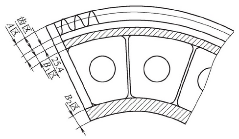
The division of ultrasonic nondestructive testing area is shown in Figure 1.
Area a: 25.4mm from the outer circular surface of the large gear to the root.
Zone B: except for zone a, the outer rim (zone 1B1) and inner flange (zone 1b2).
(1) Generally speaking, the ultrasonic inspection of large gear is arranged after rough machining or semi finishing (before tooth opening).
(2) In order to ensure effective detection, the surface roughness of the detection surface RA ≤ 6.3 μ m, and the workpiece surface shall be free of sundries that affect the ultrasonic coupling.
(3) The selection of testing instrument and probe shall meet the requirements of ASTM a 609-1991 standard, and the type a pulse reflection ultrasonic testing instrument shall be verified.
The probe adopts a longitudinal wave straight probe with a working frequency of 1-5mhz and a probe diameter of 13-28mm. If it is necessary to use angle probe to assist detection for further determining defect orientation and accurate qualitative analysis, the angle probe shall meet the working frequency of 0.4 ~ 5MHz and angle of 30 ° ~ 75 °.
(4) According to the quality requirements of different testing areas such as area a and area B of cast steel large gear, the testing sensitivity shall be strictly controlled in area a on the basis of meeting the standards of a stma609-1991.
Area a: 25.4mm behind the tooth area and root is equivalent to φ 3mm flat bottom hole.
Zone B: except zone a, the rim (zone B1) and inner flange (zone B2) are equivalent to φ 6.4mm flat bottom holes.
(5) The detection method is distance amplitude curve (DAC) contrast detection. When making the distance amplitude characteristic curve, use the standard reference block to get the FA, FB, FC points connected with DAC curve, as shown in Figure 2.
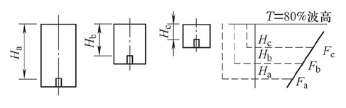
Calibration block: φ 3mm and φ 6.4mm standard flat bottom hole block.
Inspection direction: 100% ultrasonic nondestructive testing on two mutually perpendicular surfaces of wheel flange.
(6) Defect quantification includes defect record and defect quality level determination.
Defect record: (1) record according to equivalent. Area a: the area where the defect amplitude continuously exceeds the equivalent diameter of φ 3M m; area B: the area where the defect amplitude continuously exceeds the equivalent diameter of φ 6.4m. (2) Record according to the reduction of bottom wave. Areas with a continuous loss of more than 75% (12D b) of the reflected wave on the bottom (excluding the area affected by the geometric dimension). (3) Record in accordance with the extended length of the defect. The defect length was measured by half wave height method (6dB method), and the length was measured according to the probe center point.
Determination of defect quality grade: (1) determine the quality grade of defect according to the defect grade in ASTM a 609-1991 and the partition shown in Figure 1. (2) The defect records shall be comprehensively determined according to the attached table, in which area A shall be executed according to quality level 1 and area B shall be executed according to quality level 2.
(7) The wave form judgment method is used to determine the quality of defects and refer to the defect records mentioned above to determine the quality of defects. The waveform judgment method of typical casting defects is as follows.
Porosity: defect echo has high amplitude, sharp peak, narrow and fine echo. When a single pore defect exists, the bottom wave has no obvious loss. When the dense pores appear, the loss of bottom wave increases with the increase of the degree of dense pores.
Inclusions: the defect wave crest of point-shaped non-metallic inclusions is relatively round, and the amplitude is low and slow. When the probe position moves little, the defect wave disappears quickly; the defect wave of dense non-metallic inclusions presents a series of peaks, the amplitude is generally low, and there are one or two higher notch waves between the waveforms. When the probe moves, the defect wave changes within a certain range of width, and the peaks rise and fall one after another, The waveforms are confused and disordered, and the peaks of several defects are mixed into one, which are spherical or zigzag, rolling left and right. When the detection sensitivity is reduced, only a few higher defect waves appear, while the amplitude is reduced, and the bottom wave has no obvious change.
Loose: the amplitude of defect echo is lower than that of shrinkage cavity, and the reference equivalent is smaller. The defect echo is shown by clutter and grass wave. The width of defect echo is wide, the height loss of bottom wave is increased, and the number of reflection of bottom wave is reduced.
Shrinkage cavity: the defect echo has high amplitude, large reference equivalent, serious defect beam wave display, small defect wave near the main defect wave, larger defect return wave width than other types of defects, serious loss of bottom wave or no bottom wave.
Crack: the echo reflection of defect is strong, the echo front is steep, the wave peak is sharp, and the detection direction is strong. When the transverse wave angle probe detects along the vertical direction of crack extension, the defect wave is obvious, but parallel to the crack extension direction, the defect wave is not obvious.
Through the production verification of casting anatomy and metallographic analysis, the above-mentioned ultrasonic detection technology can be used to detect the internal quality of the cast steel large gear for heavy grinding and building materials equipment, and the quantitative and qualitative determination of defects can be completed.
The ultrasonic testing technology of cast steel large gear for heavy equipment not only enriches the ultrasonic testing technology of large castings in our company, but also provides reference for the ultrasonic testing of similar castings in the same industry.