1. Introduction
The pursuit of enhanced surface integrity in spur gears—critical for longevity, fatigue resistance, and reliability in industrial applications—has driven advancements in finishing technologies. Among these, spindle barrel finishing stands out due to its ability to reduce surface roughness, refine textures, improve residual stress profiles, and handle complex geometries cost-effectively. However, the interaction between abrasive media and spur gear tooth surfaces during this process remains inadequately understood, particularly at the particle-workpiece interface.

This study employs Discrete Element Method (DEM) simulations and experimental validation to dissect the influence of key parameters—gear embedment depth and rotational speed—on particle dynamics, contact forces, and surface outcomes in spindle barrel finishing of spur gears. By bridging simulation insights with empirical data, we aim to optimize process parameters for superior surface uniformity and performance.
2. Methodology
2.1. Spindle Barrel Finishing Principle
The spindle barrel finishing setup comprises a rotating drum, abrasive media (spherical ceramic particles), a spur gear workpiece, and fixtures. Simultaneous rotation of the drum and gear induces relative motion between particles and the gear, enabling material removal and surface refinement.
Key Components:
- Drum: Drives media flow via rotational motion.
- Spur Gear: Fixed on a spindle, rotating counter to the drum.
- Abrasive Media: Spherical particles (3 mm diameter) with defined material properties.
2.2. Discrete Element Modeling
Using EDEM software, a DEM model was developed to simulate particle interactions with the spur gear. The Hertz-Mindlin no-slip contact model, integrated with Archard wear theory, governed particle dynamics and wear calculations.
Model Parameters:
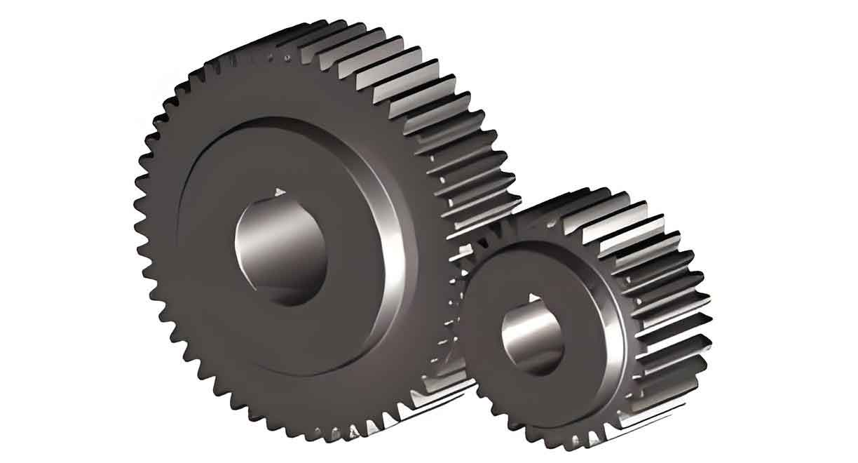
- Gear Specifications: Module m=5 mmm=5mm, teeth z=23z=23, face width b=40 mmb=40mm, pressure angle 20∘20∘.
- Material Properties:
| Material | Density (kg/m³) | Poisson’s Ratio | Shear Modulus (MPa) |
|---|---|---|---|
| Drum (Steel) | 7,850 | 0.300 | 7,940 |
| Particles (Ceramic) | 2,675 | 0.360 | 1,260 |
| Spur Gear (40Cr) | 7,870 | 0.277 | 8,080 |
Archard Wear Model:Δh=KpvHΔtΔh=HKpvΔt
Where ΔhΔh = wear depth, KK = wear coefficient, pp = normal pressure, vv = relative velocity, HH = hardness, and ΔtΔt = time.
Simulation Design:
- Variables: Gear embedment depth (h1h1: 80–140 mm) and drum speed (n1n1: 12–30 rpm).
- Output Metrics: Contact force, particle velocity, surface roughness.
3. Simulation Results
3.1. Particle Flow Dynamics
Particle flow around the spur gear exhibited three distinct phases:
- Filling Phase: Particles enter gear slots with high downward velocity (v>0.10 m/sv>0.10m/s).
- Stable Filling Phase: Particles ascend along tooth surfaces (v=0.01–0.05 m/sv=0.01–0.05m/s).
- Efflux Phase: Particles exit slots under centrifugal force (v=0.4–0.6 m/sv=0.4–0.6m/s).
Axial Flow Asymmetry:
- Front-side particle accumulation reached 192.23 mm (vs. 140 mm static height).
- Rear-side “wake” regions showed reduced particle density.
3.2. Contact Force Analysis
Key Observations:
- Phase Dependency: Stable filling phase contributed 22.45× higher contact forces than filling/efflux phases.
- Embedment Depth: A 75% increase in h1h1 (80 → 140 mm) raised contact force by 76% (Table 1).
- Speed Impact: A 150% speed increase (12 → 30 rpm) only increased contact force by 18%.
Force Distribution:
- Upper tooth surfaces endured 1.5–1.8× higher forces than lower surfaces.
- Axial force non-uniformity decreased with deeper embedment.
| Depth (mm) | Contact Force (N) | % Increase |
|---|---|---|
| 80 | 10.5 | – |
| 110 | 15.8 | 50.5% |
| 140 | 18.4 | 76.2% |
3.3. Particle Velocity Analysis
Speed Dominance:
- A 150% speed boost elevated particle velocity by 148% (Table 2).
- Upper tooth surfaces experienced 1.35–1.45× higher velocities than lower surfaces.
Depth Influence:
- Increasing h1h1 from 80 to 140 mm raised velocity by only 4%.
| Speed (rpm) | Velocity (m/s) | % Increase |
|---|---|---|
| 12 | 0.005 | – |
| 21 | 0.012 | 140% |
| 30 | 0.025 | 148% |
4. Experimental Validation
4.1. Strain Testing
A strain gauge system (DH5903N) measured dynamic stresses on spur gear surfaces. Key findings aligned with simulations:
- Cyclic Stress Patterns: Upper tooth surfaces showed periodic stress fluctuations.
- Depth Effect: Stress at h1=140 mmh1=140mm exceeded h1=80 mmh1=80mm by 59%.
4.2. Surface Roughness Evaluation
Post-processing roughness (RaRa) measurements revealed:
- Axial Uniformity: At h1=140 mmh1=140mm, axial roughness reduction reached 62% (vs. 17% at 80 mm).
- Speed Impact: Higher speeds enhanced roughness reduction by 5.36× on lower tooth surfaces.
| Depth (mm) | Upper Tooth (%) | Lower Tooth (%) |
|---|---|---|
| 80 | 17 | 36 |
| 140 | 62 | 55 |
5. Discussion
5.1. Parameter Optimization for Spur Gears
- Embedment Depth: Maximizing h1h1 enhances contact force and axial uniformity but has diminishing returns.
- Rotational Speed: Higher speeds amplify particle velocity, critical for rapid material removal.
Trade-offs: Balancing depth and speed is essential to avoid excessive wear or energy consumption.
5.2. Asymmetry in Tooth Surface Loading
The inherent asymmetry in upper/lower tooth loading (1.5–1.8× force difference) suggests design modifications—e.g., asymmetric tooth profiles or media composition—to mitigate uneven wear in spur gears.
6. Conclusion
- Phasic Particle Behavior: The stable filling phase dominates material removal, contributing >22× higher forces than other phases.
- Depth vs. Speed: Embedment depth primarily governs contact force (+76%), while speed drives particle velocity (+148%).
- Surface Uniformity: Deep embedment (h1=140 mmh1=140mm) reduces axial roughness variability from 17–36% to 55–62%.
Future Work: Integrating machine learning for real-time parameter adjustment could further optimize spindle barrel finishing for spur gears in high-precision applications.
