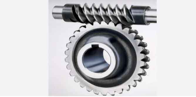
The geometry and design of worm gears play a crucial role in their performance and efficiency. Here are some key aspects to consider for optimal worm gear performance:
- Tooth Profile: Worm gears typically have a trapezoidal tooth profile. The tooth shape is designed to ensure smooth engagement and disengagement between the worm and the gear. The profile should be accurately manufactured to minimize friction and wear during operation.
- Helix Angle: The helix angle of the worm gear refers to the angle between the tooth surface and the gear axis. It determines the efficiency and load-carrying capacity of the gear. A larger helix angle results in higher gear efficiency but can reduce the gear’s load-carrying capacity. Balancing these factors is essential in the design process.
- Lead Angle: The lead angle of the worm gear is the angle between the helix line and the gear axis. It is a critical parameter as it influences the contact pattern and meshing behavior of the worm gear. Proper lead angle design is essential to avoid gear tooth interference and ensure smooth operation.
- Module and Pitch Diameter: The module is a measure of the size of the worm gear teeth, and the pitch diameter is the diameter at which the gear and the worm mesh. Proper selection of the module and pitch diameter is crucial to achieve the desired gear ratio and ensure efficient power transmission.
- Number of Starts: Worm gears can have single or multiple starts. A single-start worm has one tooth wrapped around its circumference, while a multiple-start worm has multiple teeth. Multiple-start worms provide higher gear reduction ratios and better load-carrying capacity.
- Material Selection: The choice of material for the worm gear is essential to ensure durability, strength, and wear resistance. Common materials include alloy steels, bronze, and stainless steel, depending on the application and environmental conditions.
- Lubrication: Proper lubrication is vital to reduce friction and wear between the worm and gear. The lubricant should be selected based on the operating conditions and load requirements to ensure smooth and efficient operation.
- Center Distance: The center distance between the worm and gear should be carefully calculated to ensure proper meshing and minimize backlash.
- Backlash Control: Backlash in worm gears can cause vibration and reduce efficiency. Proper design and manufacturing techniques can help control backlash and ensure precise motion transmission.
- Heat Treatment: Heat treatment processes such as carburizing and quenching can be applied to improve the hardness and wear resistance of the worm gear teeth.
The design of worm gears involves a careful balance of these parameters to achieve the desired performance characteristics, including smooth operation, high efficiency, and load-carrying capacity. Advanced computer-aided design (CAD) and simulation tools are often used to optimize the design and ensure the best performance for specific applications.
