In order to verify the kinematic model, during the gear hobbing test, the position track of the cylindrical gear is collected through the Siemens 840D system of the gear hobbing CNC machine tool. The technological parameters of cylindrical gear hobbing test are shown in the table.
| Parameters | Specifications |
| Module of gear and hob/mm | 3.175 |
| Number of gear teeth | 30 |
| Gear material | 20CrNi2Mo steel |
| Pressure angle of gear and hob/(°) | 0 |
| Gear helix angle / (°) | 20 |
| Outer diameter of gear/mm | 102.25 |
| Tooth width/mm | 56.7 |
| Hob material | ASP2052 High Speed Steel |
| Hob length/mm | 102 |
| Global rake angle of hob/(°) | 0 |
| Number of chip holding grooves of hob | 14 |
| Hob tip fillet radius/mm | 38.1 |
| Cutting depth/mm | 7.143 |
| Cutting speed/(m · min ^ – 1) | 55 |
| Feed rate/(mm · r ^ – 1) | 3.0 |
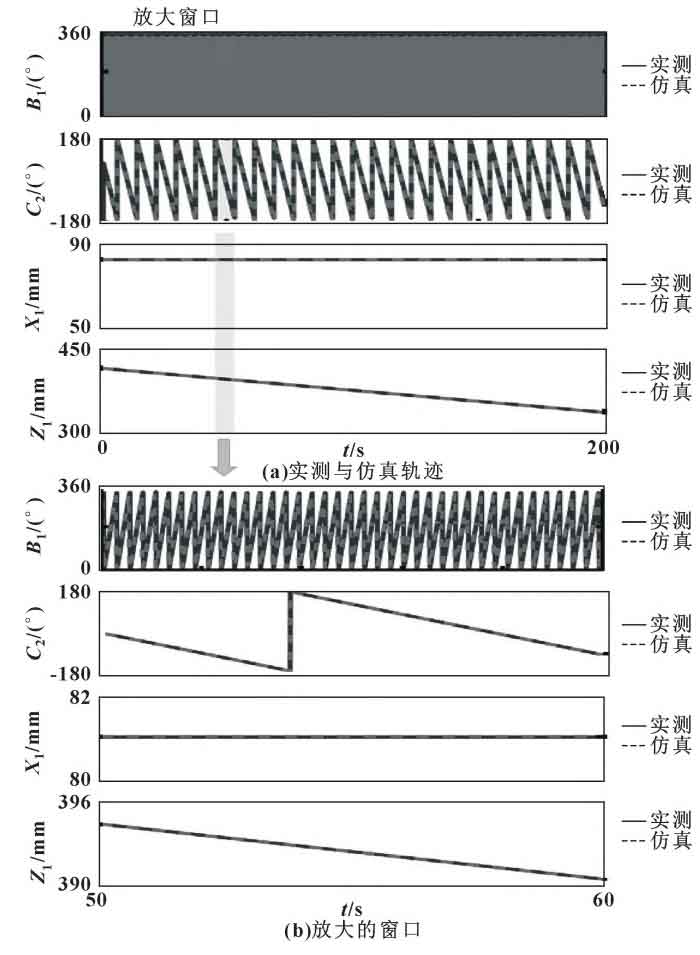
For axes B1, C2, X1 and Z1, the comparison between the measured and predicted motion tracks of cylindrical gears is shown in the figure. It can be seen that the feed drive motion is accurately modeled and predicted, which is essential for the correct analysis of kinematics and CWE conditions.