
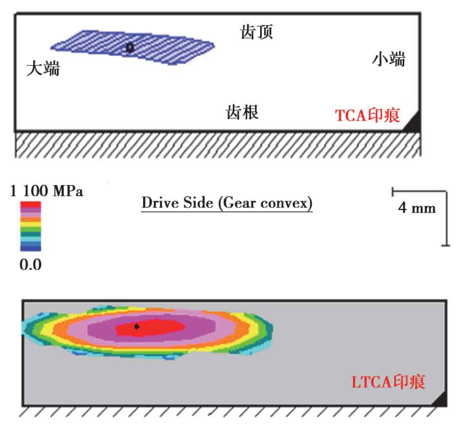
Through ABAQUS loading characteristic analysis, the contact spots on the convex surface of the big wheel are compared with the contact marks on the convex surface of the big wheel calculated by kimos tooth contact analysis (TCA) and load-bearing contact analysis (LTCA) at 450nm, so as to further verify the accuracy of the derivation of the tooth surface model. Kimos calculation results are shown in Figure 1.
According to the hypoid gear solid model established above, the finite element meshing model is established through ABAQUS, as shown in Figure 2. In order to save calculation time, 11 teeth are selected for the big wheel and full teeth for the small wheel. RP1 and RP2 are the reference coupling points of the small wheel and the large wheel respectively; The concave surface of the small wheel is the active contact surface, and the convex surface of the big wheel is the driven contact surface. The contact pairs are established respectively with the meshing tooth surfaces, and the contact characteristics are set up without friction and hard contact; The normal meshing process of hypoid gears is simulated by preloading and normal meshing analysis steps. The torque of the big wheel is 450nm, the young’s modulus is 210gpa, and the Poisson’s ratio is 0.3.
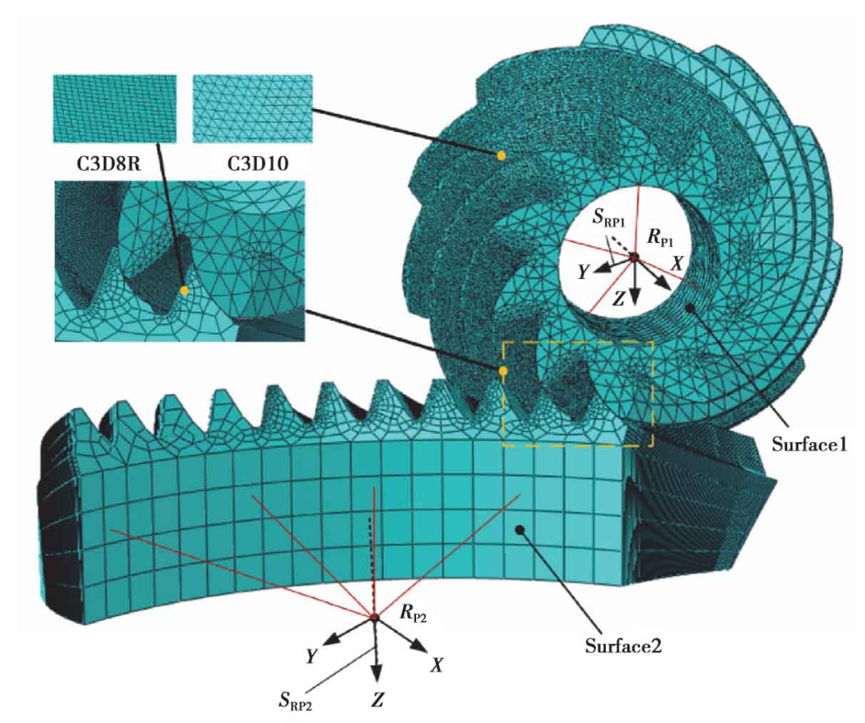
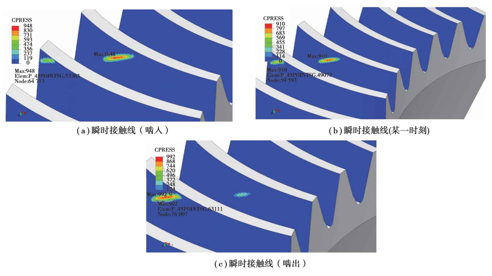
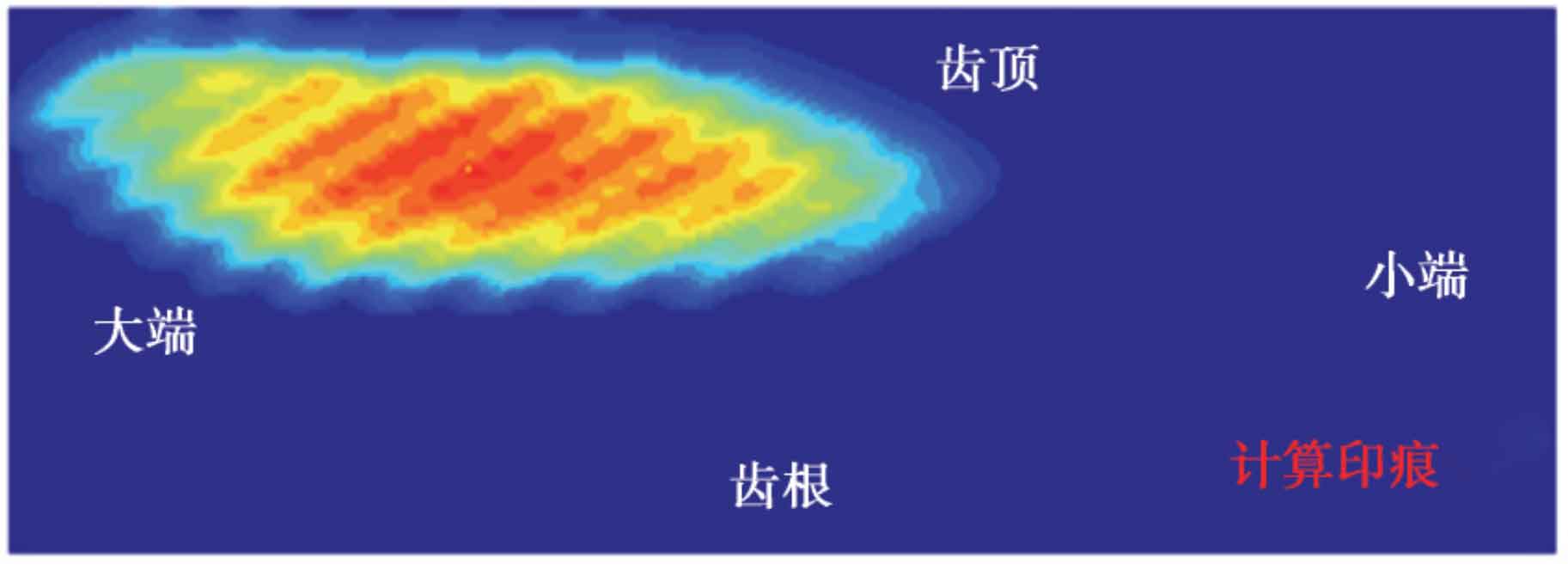
Figure 3 shows the instantaneous contact line of the convex surface of the big wheel at three times from meshing in to meshing out. Figure 4 shows the contact marks on the convex surface of the big wheel. It can be seen from the figure that the location of the theoretical TCA impression calculated by kimos is basically the same as that calculated by finite element method; The contact mark calculated by finite element method is basically consistent with the position and size calculated by kimos through LTCA, which further verifies the correctness of the tooth surface.
In the design process of the location and size of the actual contact mark, factors such as heat treatment process and shafting support deformation should be considered. By adjusting the parameters of the cutter and machine tool, the position of the design impression can be adjusted to ensure that the area of the meshing impression is located in the teeth after the heat treatment deformation and support deformation, so as to improve the contact state of the hypoid gear.
Through the comparison of tooth surfaces and the verification of contact marks, the modeling method of hypoid gear based on tool ns normal datum is accurate and feasible.