Using the finite element simulation method to analyze the actual machining of gears, the force of the tool in the actual machining process and the change of other specific cutting performance of the tool can be analyzed. By analyzing the cutting force under different cutting parameters, the influence of cutting parameters on cutting results is comprehensively considered.

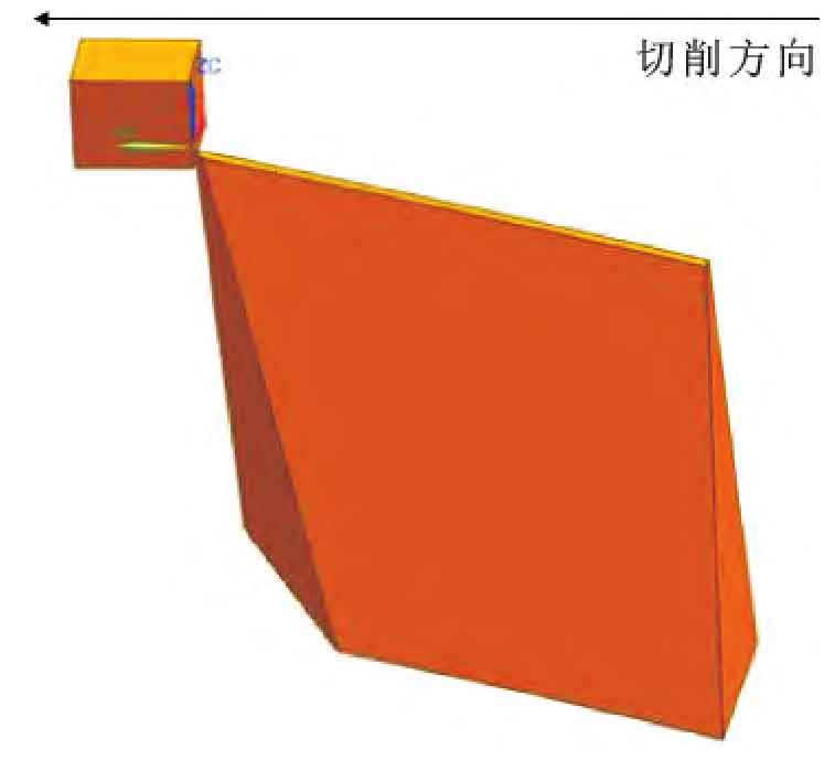
It is very complicated to simulate the machining process in detail, so it is necessary to simplify the machining model. Because the cutting process of each tooth slot of the gear is the same, only one segment of tooth surface needs to be simulated. The radius of curvature of the tooth profile arc of the variable hyperbolic arc gear to be processed is large, so the workpiece can be treated as an approximate straight line and replaced by a rectangular parallelepiped during simulation, as shown in Fig. 1.
| Material parameters | 45 steel | WC |
| Density / (g · cm ^ – 3) | 7.89 | 11.9 |
| Elastic modulus / GPa | 209 | 650 |
| Poisson’s ratio | 0.269 | 0.25 |
| Temperature conductivity / (w · m ^ – 1 · ° C ^ – 1) | 5.2 | 35 |
| Melting temperature / ° C | 1495 | — |
| Thermal expansion coefficient / ° C ^ – 1 | 11.59X10^-6 | — |
| Parameters | Parameter value |
| A / MPa | 570.47 |
| B / MPa | 689.65 |
| C( Epsilon dot zero = 1) | 0.014 |
| n | 0.3496 |
| m | 4.949 |
| Parameters | D1 | D2 | D3 | D4 | D5 |
| Parameter Value | -0.09 | 0.25 | -0.5 | 0.014 | 3.87 |
The constitutive relation of materials is very important for finite element simulation, because it represents the essential properties of materials to a certain extent. In this type of simulation, Johnson cook model has good fitting and numerical stability to the mechanical behavior of metal, and can be conveniently applied to the finite element analysis model. Therefore, the senior engineer team of ZY gear adopts Johnson cook model and sets the workpiece material as 45 steel. The material parameters and constitutive model parameters are shown in table 1-3. The tool material is set as WC (tungsten carbide) material. In the simulation process, the tool is set as a rigid body model to improve the cutting efficiency.

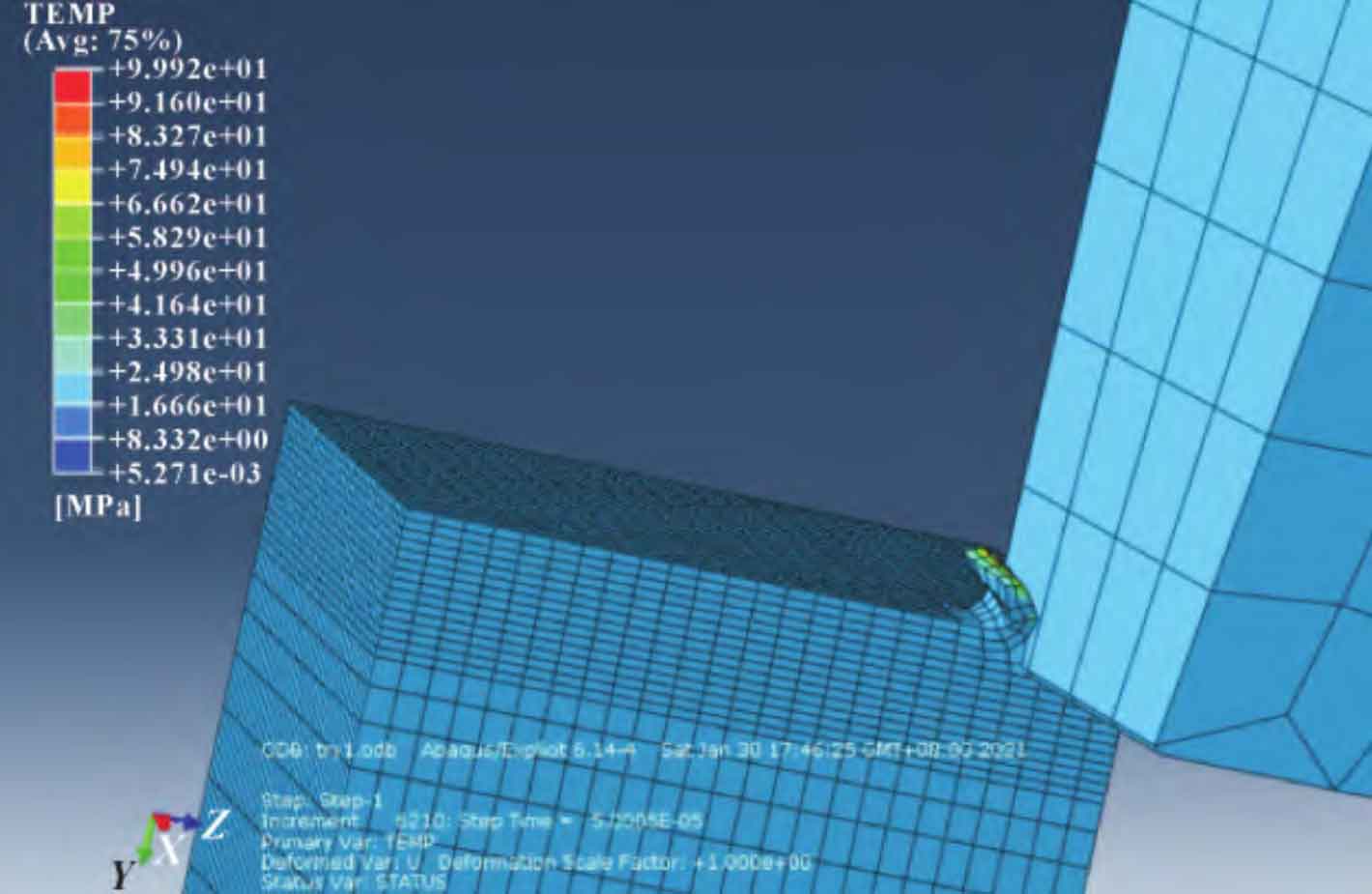
After setting the material module, analysis step and other modules, when the simulation is completed, the simulation of each time in the cutting process of the milling cutter can be viewed in the result module of ABAQUS software, and the results of the simulation output can be obtained, as shown in Fig. 2.
