
In modern mechanical transmission systems, herringbone gears play a crucial role due to their high load-bearing capacity, smooth operation, and minimal axial forces. These advantages make them ideal for applications in marine and aerospace engineering. However, over time, tooth surface wear can significantly impact the dynamic behavior of herringbone gear systems, leading to increased vibrations, noise, and potential failure. In this study, I aim to explore the vibration characteristics of herringbone gears under the influence of tooth surface wear, combining theoretical modeling and experimental validation to provide insights into the wear-induced dynamic changes.
The dynamic performance of herringbone gears is influenced by various factors, including meshing stiffness, errors, and wear. Wear, in particular, is a progressive process that alters the tooth profile, affecting the meshing conditions and ultimately the system’s vibration response. Understanding this relationship is essential for predictive maintenance and design optimization. Here, I develop a comprehensive dynamic model that incorporates tooth surface wear, meshing stiffness variations, and errors, and I validate it through experimental tests on a herringbone gear transmission system.
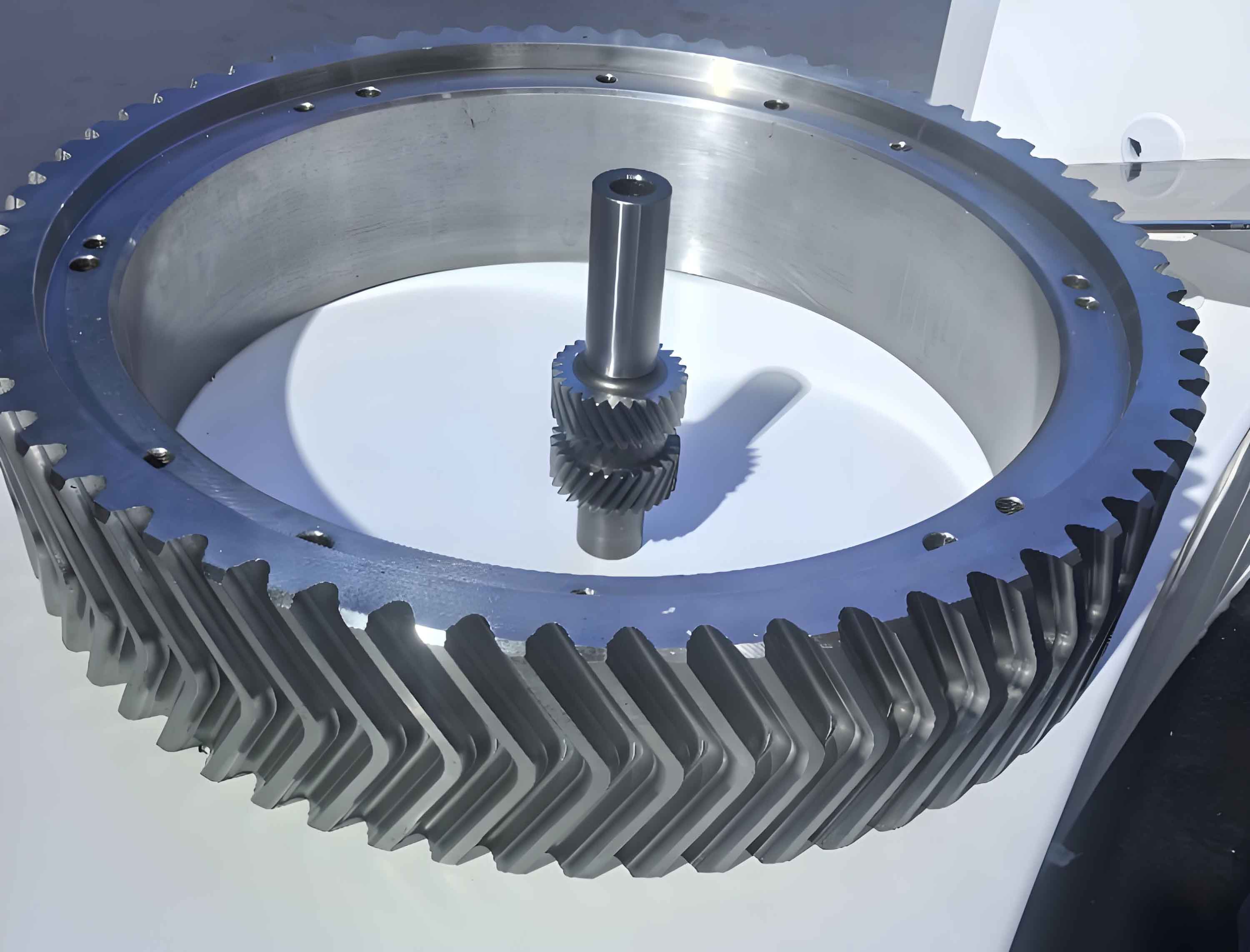
To begin, I establish a theoretical framework for analyzing herringbone gears. The wear process on tooth surfaces is modeled using adhesive wear principles, where the cumulative wear depth at a contact point is calculated based on the Archard wear equation. For herringbone gears, this wear accumulation can be expressed as:
$$ h_{i,j} = h_{i-1,j} + 4 a p k_{\iota} \frac{|v_1 – v_2|}{v_j} $$
where \( h_{i,j} \) is the wear depth at step \( i \) for gear \( j \) (with \( j = 1 \) or \( 2 \)), \( a \) is the contact half-width, \( p \) is the Hertzian contact pressure, \( k_{\iota} \) is the wear rate, and \( v_1, v_2 \) are the rolling velocities of the driving and driven herringbone gears, respectively. This wear model accounts for the relative sliding between meshing teeth, which is common in herringbone gear operation due to their helical nature.
The wear process typically follows three stages: running-in wear, steady wear, and severe wear. In herringbone gears, the running-in stage involves initial surface smoothing, which can temporarily reduce vibrations. However, as wear progresses, the tooth profile deviations increase, leading to changes in meshing stiffness and dynamic response. To quantify this, I calculate the time-varying meshing stiffness of herringbone gears, considering bending, shear, axial compression, Hertzian contact deformation, and foundation effects. The total deformation at the load application point along the meshing line is given by:
$$ \delta_{\Xi j} = \delta_{Br,j} + \delta_{Bt,j} + \delta_{R,j} + \delta_{pe,j} + h_{i,j} $$
Here, \( \delta_{Br,j} \) is the bending deformation, \( \delta_{Bt,j} \) is the shear deformation, \( \delta_{R,j} \) is the foundation deformation, \( \delta_{pe,j} \) is the contact deformation, and \( h_{i,j} \) is the wear depth. The individual components are derived using material mechanics principles. For instance, the bending deformation for a herringbone gear tooth can be expressed as:
$$ \delta_{Br,j} = \frac{12 F_N \cos^2 \beta}{E b s_F^3} \left[ h_x h_r (h_x – h_r) + \frac{h_r^3}{3} \right] $$
where \( F_N \) is the normal load, \( \beta \) is the helix angle of the herringbone gears, \( E \) is Young’s modulus, \( b \) is the face width, \( s_F \) is the tooth thickness at the root, and \( h_x, h_r \) are geometric parameters related to the tooth profile. Similar expressions are used for shear and other deformations. The meshing stiffness \( k_m \) for herringbone gears is then computed as the reciprocal of the total deformation summed over all contact pairs:
$$ k_m = \frac{F_N}{\sum_{i=1}^{N} \delta_{\Xi i}} $$
where \( N \) is the number of meshing pairs. This stiffness varies with time due to the changing contact conditions caused by wear in herringbone gears.
In addition to stiffness, tooth surface wear introduces profile deviations that act as meshing errors. The cumulative profile error for herringbone gears after \( K \) meshing cycles is:
$$ (GK)_{p,g} = (G^0_T)_{p,g} – \sum_{i=1}^{K} (h^k_i)_{p,g} $$
where \( (G^0_T)_{p,g} \) is the initial profile error for the driving (p) or driven (g) herringbone gear, and the summation represents the wear accumulation. These errors are transformed into meshing error functions using Fourier series:
$$ e_t = \sum_{i=1}^{M} [e_{ai} \sin(2\pi i f_m t + \phi_{ei})] $$
with \( e_{ai} = \frac{(GK)_p}{\cos \beta} + \frac{(GK)_g}{\cos \beta} \), where \( f_m \) is the meshing frequency and \( M \) is the harmonic order. This error excitation is critical in the dynamic analysis of herringbone gears.
To model the dynamic behavior, I develop a 12-degree-of-freedom (DOF) bending-torsional-axial coupled dynamic model for a herringbone gear system. The model includes translations in x, y, z directions and rotations about the z-axis for both driving and driven herringbone gears. The equations of motion are derived using Lagrange’s equations, considering the meshing forces, damping, and stiffness. The relative displacement along the meshing line for the left and right helical pairs of herringbone gears is:
$$ \delta_{mi}(t) = [(y_{pi} – y_{gi}) \cos \psi + (x_{pi} – x_{gi}) \sin \psi + r_{pi} \theta_{pi} + r_{gi} \theta_{gi}] \cos \beta + (z_{pi} – z_{gi}) \sin \beta – e_t $$
where \( \psi = -\phi – \alpha_t \) is the installation phase angle, \( \phi \) is the angle between the meshing line and y-axis, \( \alpha_t \) is the transverse pressure angle, and \( \beta \) is the helix angle. The dynamic meshing force for herringbone gears includes elastic and damping components:
$$ F_{pi} = k_{mi} \delta_{mi}(t) + c_{mi} \dot{\delta}_{mi}(t) + k_{mi} e_{ti} + c_{mi} \dot{e}_{ti} $$
Here, \( k_{mi} \) is the time-varying meshing stiffness, and \( c_{mi} \) is the damping coefficient for herringbone gears, calculated as \( c_m = 2\xi \sqrt{\frac{k_m r_1^2 r_2^2 I_1 I_2}{r_1^2 I_1 + r_2^2 I_2}} \), with \( \xi = 0.1 \) as the damping ratio. The equations of motion for each herringbone gear component are:
$$ m_{pi} \ddot{x}_{pi} + c_{pxi} \dot{x}_{pi} + k_{pxi} f(x_{pi}) = -F_x $$
$$ m_{pi} \ddot{y}_{pi} + c_{pyi} \dot{y}_{pi} + k_{pyi} f(y_{pi}) = -F_y $$
$$ m_{pi} \ddot{z}_{pi} + c_{pzi} \dot{z}_{pi} + k_{pzi} f(z_{pi}) = F_z $$
$$ I_{pi} \ddot{\theta}_{pi} = -F_{pi} R_{pi} \cos \beta – F_{fi} R_{pi} \cos \beta + T_p / 2 $$
$$ m_{gi} \ddot{x}_{gi} + c_{gxi} \dot{x}_{gi} + k_{gxi} f(x_{gi}) = F_x $$
$$ m_{gi} \ddot{y}_{gi} + c_{gyi} \dot{y}_{gi} + k_{gyi} f(y_{gi}) = F_y $$
$$ m_{gi} \ddot{z}_{gi} + c_{gzi} \dot{z}_{gi} + k_{gzi} f(z_{gi}) = -F_z $$
$$ I_{gi} \ddot{\theta}_{gi} = -F_{pi} R_{gi} \cos \beta – F_{fi} R_{gi} \cos \beta + T_g / 2 $$
where \( F_x, F_y, F_z \) are the force components derived from the meshing force. The system dynamics are solved using the Runge-Kutta method to obtain time-domain responses for herringbone gears under different wear conditions.
To validate the theoretical model, I conduct experimental tests on a herringbone gear transmission system. The test rig consists of a servo-driven gearbox and a test gearbox with herringbone gear pairs. The herringbone gears are manufactured from 17CrMnTi steel, carburized and quenched to a surface hardness of 58 HRC. Key parameters of the herringbone gears are summarized in Table 1.
| Parameter | Driving Gear | Driven Gear |
|---|---|---|
| Number of Teeth | 34 | 31 |
| Mass (kg) | 1.63 | 1.28 |
| Moment of Inertia (kg·m²) | 0.0028 | 0.0019 |
| Transverse Module (mm) | 3.464 | |
| Transverse Pressure Angle (°) | 22.79 | |
| Helix Angle (°) | 30 | |
| Face Width (mm) | 12×2+10 | |
| Backlash (mm) | 0.05 | |
| Material | 17CrMnTi | |
The test conditions include input speeds of 100, 200, 300, 400, and 500 rpm, and input torques of 100, 150, and 200 Nm. Vibration acceleration is measured at bearing locations on the input and output shafts using Kistler Type 870350M5 accelerometers. The herringbone gears are tested at different running cycles: initial operation, 3×10⁶, 5×10⁶, 1×10⁷, and 5×10⁷ cycles, to simulate wear progression.
The results from the theoretical model and experiments are analyzed to understand the vibration characteristics of herringbone gears. First, I examine the vibration displacement under an input speed of 500 rpm and torque of 200 Nm for different running cycles. As shown in Table 2, the vibration displacement amplitudes for herringbone gears in x and y directions initially decrease during the running-in wear stage and then increase with further wear.
| Running Cycles | Driving Gear (x) | Driving Gear (y) | Driven Gear (x) | Driven Gear (y) |
|---|---|---|---|---|
| Initial | 1.2e-5 | 1.8e-5 | 1.1e-5 | 1.5e-5 |
| 3×10⁶ | 1.0e-5 | 1.6e-5 | 0.9e-5 | 1.3e-5 |
| 5×10⁶ | 1.3e-5 | 2.0e-5 | 1.2e-5 | 1.7e-5 |
| 1×10⁷ | 1.5e-5 | 2.3e-5 | 1.4e-5 | 2.0e-5 |
| 5×10⁷ | 2.0e-5 | 3.0e-5 | 1.9e-5 | 2.5e-5 |
Similarly, the vibration velocity for herringbone gears shows a trend of initial reduction followed by an increase. For example, at 500 rpm and 200 Nm, the velocity amplitude along the meshing line decreases by about 11.2% from initial to 3×10⁶ cycles, but then increases by 1.6 times from 3×10⁶ to 5×10⁷ cycles. This can be expressed mathematically as:
$$ v_{\text{mesh}} = v_0 \left(1 – 0.112\right) \quad \text{for running-in} $$
$$ v_{\text{mesh}} = v_0 \left(1 + 1.6\right) \quad \text{for steady wear} $$
where \( v_0 \) is the initial velocity. The vibration acceleration amplitudes from experiments are summarized in Table 3 for different input conditions. It is observed that for herringbone gears, at constant torque, acceleration amplitude increases with speed, but at constant speed, it remains relatively unchanged with torque variations.
| Input Speed (rpm) | Input Torque (Nm) | Acceleration Amplitude |
|---|---|---|
| 100 | 100 | 0.05 |
| 200 | 100 | 0.12 |
| 300 | 100 | 0.25 |
| 400 | 100 | 0.45 |
| 500 | 100 | 0.70 |
| 500 | 150 | 0.71 |
| 500 | 200 | 0.72 |
The theoretical predictions align well with experimental data. For instance, at 500 rpm and 200 Nm after 1×10⁷ cycles, the theoretical vibration acceleration for the driving herringbone gear ranges from -0.12 to 0.12 m/s², matching the experimental range. This validates the dynamic model for herringbone gears under wear conditions.
Further analysis involves the meshing stiffness variations due to wear in herringbone gears. As wear accumulates, the stiffness decreases, affecting the dynamic response. The stiffness reduction can be quantified as:
$$ k_m^{\text{worn}} = k_m^{\text{new}} – \Delta k $$
$$ \Delta k = \alpha \sum h_{i,j} $$
where \( \alpha \) is a proportionality constant related to the gear geometry. For herringbone gears, this stiffness change influences the natural frequencies and vibration modes. The dynamic equations can be linearized around the mean stiffness to analyze frequency responses:
$$ [M] \{\ddot{x}\} + [C] \{\dot{x}\} + [K] \{x\} = \{P\} $$
where [M], [C], and [K] are mass, damping, and stiffness matrices for the herringbone gear system. Solving this eigenvalue problem provides insights into how wear shifts the resonant frequencies of herringbone gears.
In discussion, the wear-induced vibrations in herringbone gears are attributed to several mechanisms. First, tooth profile deviations from wear increase meshing errors, leading to impact forces during engagement. Second, reduced meshing stiffness lowers the system’s natural frequency, potentially exciting lower-frequency modes. Third, the asymmetrical wear between left and right helical halves of herringbone gears can cause axial force imbalances, contributing to torsional vibrations. These effects are particularly critical in high-speed applications where herringbone gears are often used.
To mitigate wear-related vibrations in herringbone gears, potential strategies include using advanced lubricants, surface coatings, or adaptive control systems. Regular monitoring of vibration signals can also help in early wear detection. The model developed here can be extended to include thermal effects or nonlinearities for more accurate predictions.
In conclusion, this study demonstrates the significant impact of tooth surface wear on the vibration characteristics of herringbone gears. Through a combined theoretical and experimental approach, I show that wear causes initial vibration reduction during running-in, followed by a progressive increase in displacement, velocity, and acceleration amplitudes. The dynamic model effectively captures these trends, providing a tool for analyzing herringbone gear systems in practical applications. Future work could explore the effects of different wear patterns or environmental conditions on herringbone gear dynamics.
The key findings emphasize the importance of considering wear in the design and maintenance of herringbone gears. By understanding these vibration characteristics, engineers can optimize herringbone gear transmissions for longer service life and improved reliability. The use of herringbone gears in critical systems necessitates such detailed dynamic analyses to ensure operational safety and efficiency.