
Set the initial state of the spur gear pair to zero, set the rectangular peeling at the pitch circle of the driving wheel, and the width HS of the peeling area is 0.5 mm. Other parameters are shown in Table 1 to table 3,
| Parameters | Driving wheel | Driven wheel |
| Modulus (M / mm) | 2 | 2 |
| Number of teeth (z) | 19 | 48 |
| Pressure angle α (/ °) | 20 | 20 |
| Tooth width (L / mm) | 16 | 16 |
| Elastic modulus (E / GPA) | 206 | 206 |
| Poisson’s ratio μ | 0.3 | 0.3 |
| Parameters | Value |
| Temperature rise coefficient μ | 0.83 |
| Tooth surface friction factor FM | 0.01 |
| Thermal conductivity GI (/ J · M-1 · S-1 ·℃ – 1) | 46.47 |
| Gear density ρ i(/ kg·m-3) | 7833 |
| Material specific heat capacity CI (/ J · kg-1 ·℃ – 1) | 481.48 |
| Calculation coefficient ψ | 1.128 |
| Surface roughness (SI)/ μ m | 0.8 |
| Linear expansion coefficient of material λ | 1.16X10^-5 |
| Body temperature Δ M /℃ | 100 |
| Temperature of drive shaft Δ roi /℃ | 40/45 |
| Base circle position temperature Δ rbi /℃ | 100 |
| Parameters | Value |
| Driving wheel mass M1 / kg | 0.96 |
| Driven wheel mass M2 / kg | 2.88 |
| Driving wheel moment of inertia I1 (/ kg · m2) | 4.3659X10^-4 |
| Driven wheel moment of inertia I2 (/ kg · m2) | 8.3620X10^-4 |
| Motor moment of inertia IF1 (/ kg · m2) | 0.0021 |
| Load moment of inertia IF2 (/ kg · m2) | 0.0105 |
| Motor input torque M1 (/ N · m) | 11.9 |
| Load output torque M2 (/ N · m) | 48.9 |
| Torsional stiffness of gear shaft KFI (/ N · m-1) | 4.4X10^4 |
| Gear shaft torsional damping CFI (/ N · s · m-1) | 5.0X10^5 |
| Bearing support stiffness Ksi (/ N · m-1) | 6.56X10^7 |
| Bearing support damping CSI (/ N · s · m-1) | 1.8X10^5 |
| Input shaft rotation frequency FR / Hz | 30 |
| Engagement frequency FM / Hz | 570 |
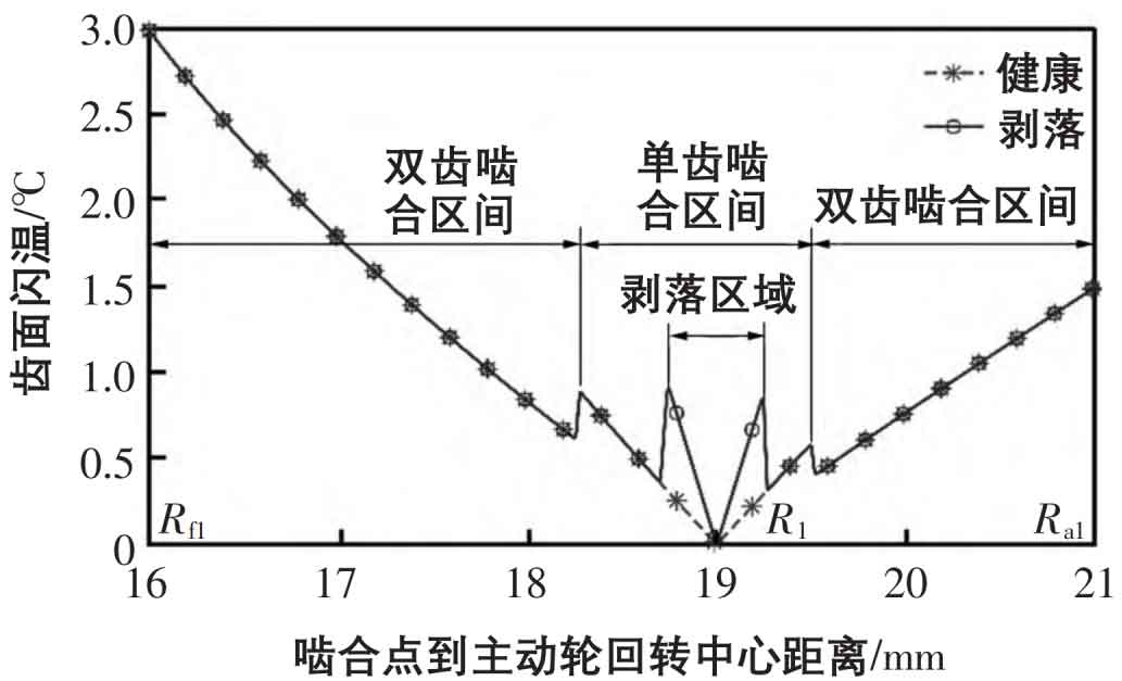
The Runge Kutta method is used to solve the system equations of spur gears. As shown in Fig. 1, the two gears at the meshing node are pure rolling, the friction force is almost zero, and no friction heat is generated, which makes the flash temperature of the spur gear pair at the meshing node extremely insignificant. When the actual meshing point is gradually away from the meshing node, the relative sliding speed increases, the friction force increases, and more heat is generated, resulting in an increase in the flash temperature of the tooth surface; Moreover, due to the alternation of the single and double tooth meshing interval and the reduction of the effective tooth width when the peeling fault enters the meshing, the load on the unit tooth width of the gear teeth will suddenly change, and the tooth surface flash temperature will suddenly change in the single and double tooth meshing interval and when the peeling fault enters and exits the meshing.
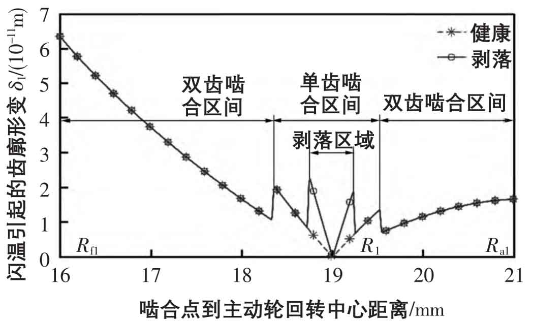
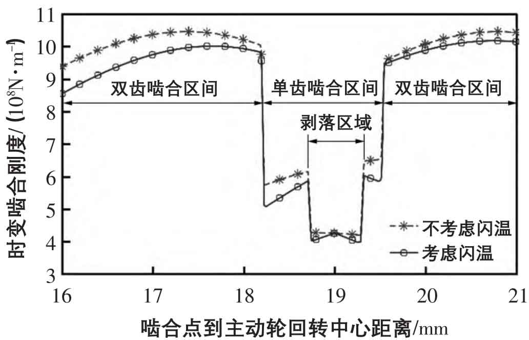
As shown in Fig. 2, the change trend of the tooth profile deformation of the driving gear is consistent with that of the flash temperature curve, which is that the value of the deformation variable at the meshing node is almost zero. When the driving gear is far from the meshing node, the tooth profile deformation will increase under the influence of the flash temperature, and the effective tooth width will suddenly change with the meshing between the single and double teeth and the peeling area. As shown in Fig. 3, when the tooth surface flash temperature is considered, the comprehensive meshing stiffness of the spur gear pair shows a decreasing trend as a whole. At the meshing node, the comprehensive meshing stiffness of the spur gear pair and the meshing stiffness without considering the tooth surface flash temperature have a small difference because the flash temperature stiffness is very large. In the process that the actual meshing point is far from the meshing node, the stiffness change value increases.
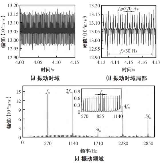
The vibration signal of spalling fault spur gear pair considering the influence of flash temperature is shown in Fig. 4. Because the meshing stiffness of the peeling area is reduced when it is engaged, the spur gear pair generates pulse impact vibration, resulting in the pulse impact peak with frequency of the rotating shaft frequency FR and the pulse impact peak with frequency of the meshing frequency domain FM in the vibration time domain, and the high octave frequency NFM (n = 1, 2, 3…) and sideband of the meshing frequency also appear in the frequency domain signal, and the interval between the sidebands is the rotating shaft frequency.
Based on block flash temperature theory, the dynamic equation of spur gear pair system considering flash temperature is established, and the following conclusions are obtained:
1) During the meshing transmission of spur gear pair, the sliding friction between the two wheels generates heat, and the spur gear profile is thermally deformed, resulting in flash temperature and stiffness;
2) The two gears at the meshing node are pure rolling, the heat generated by friction is small, and the deformation of the corresponding spur gear tooth profile is small, so that the flash temperature stiffness of the two gears at the meshing node is large, while the comprehensive meshing stiffness of the spur gear pair decreases as a whole, and as the actual meshing point is away from the meshing node, the meshing stiffness of the spur gear pair decreases and the amplitude increases;
3) When the tooth surface flash temperature is considered, the spalling fault spur gear pair is affected by the meshing stiffness. There is obvious periodic pulse vibration in the time domain of the vibration of the spur gear pair, and the frequency in the frequency domain is consistent with the rotating shaft frequency fr. the repetition frequency of the adjacent impact peak is the meshing frequency FM of the spur gear pair, accompanied by the high multiple frequency NFM (n = 1, 2, 3…) and the sideband, and the interval of the sideband is the rotating shaft frequency.