Firstly, the natural vibration characteristics of the coupled system are solved. By simplifying the dynamic equation of multi-stage gear transmission box coupling in the formula and ignoring its damping and internal and external excitation, the undamped free vibration equation of the system in free state can be obtained as follows:

The eigenvalue problem corresponding to the above equation is as follows:

Where, ω I and χ I are the i-th natural frequency and mode vector of the system, respectively. Note that the unit of ω I is rad / s, not Hz.
The formula can be solved by eig function in MATLAB, and the function call mode is [V, D] = eig (k, m). Where K and m are the stiffness matrix and mass matrix of the dynamic system respectively; each column of V is a natural mode vector; D is a diagonal matrix composed of ω 2I.
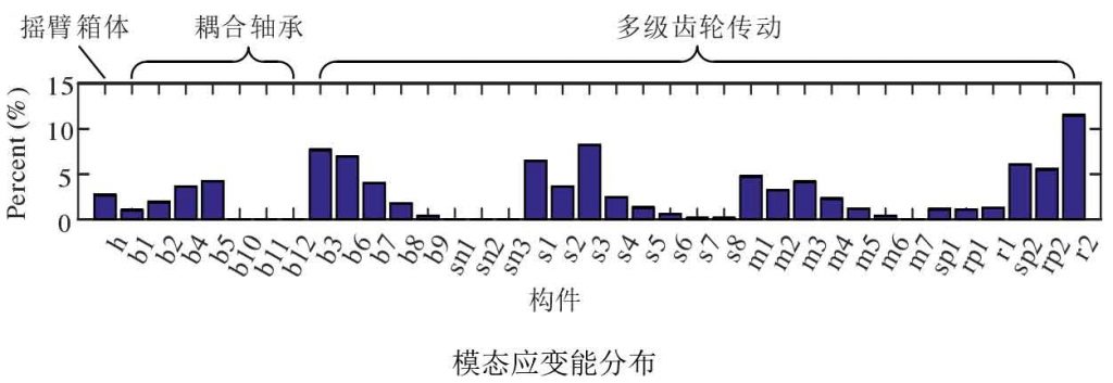
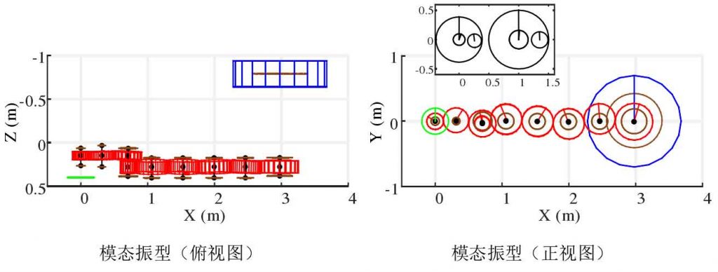
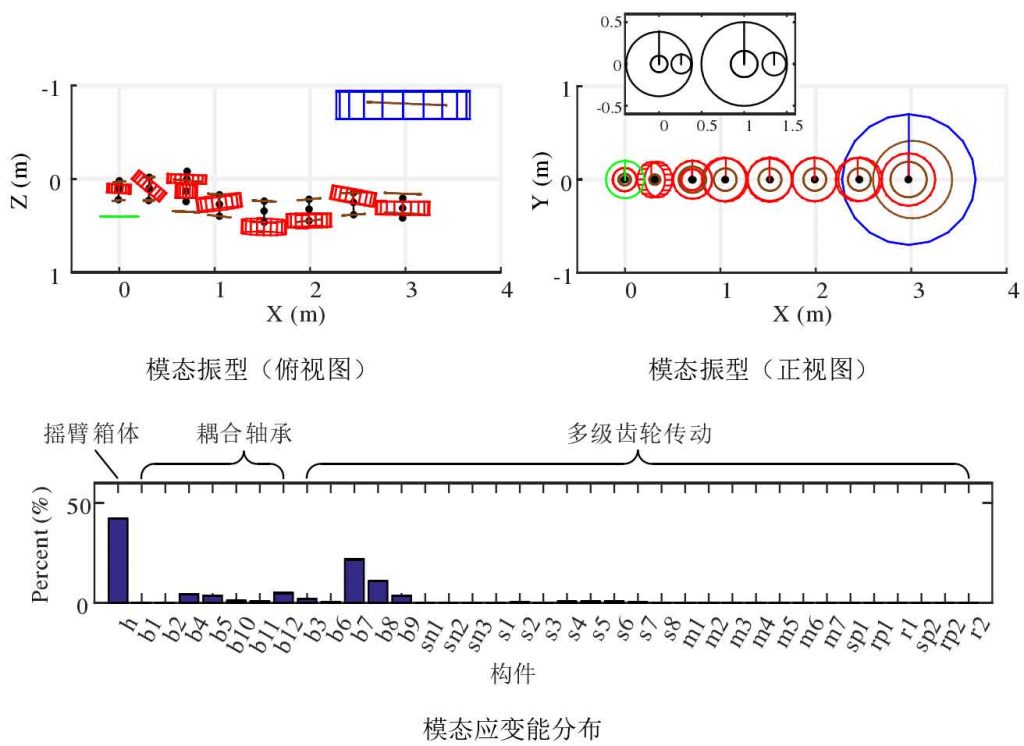
For the vibration mode of the coupling system, according to whether the rocker box has significant overall deformation, the vibration mode can be divided into two categories: significant deformation mode of the rocker box (x) and no significant deformation mode of the rocker box, the latter is also known as significant deformation mode of multi-stage gear transmission (C). Figure 1 shows the typical vibration mode diagram and modal strain energy distribution representing various vibration modes. The abscissa component h of modal strain energy represents rocker box, Bi represents bearing I, Si represents gear shaft I, SNI represents elastic torque shaft I, MI represents fixed shaft gear pair I, SPI represents outer meshing pair of stage I planetary gear train, RPI represents inner meshing pair of stage I planetary gear train, RI represents inner meshing pair of stage I planetary gear train Elastic support for ring gear of stage planetary gear train. All components are divided into rocker box, coupling bearing and multi-stage gear transmission. Coupling bearing refers to the bearing connecting multi-stage gear transmission and rocker box.
The second and 25th modes belong to the significant deformation mode X of the rocker box. In the vibration mode of the second mode, the deformation of the rocker box results in the implicated motion of the multi-stage gear drive, but there is no strain energy in the multi-stage gear drive, as shown in Fig. 1 (a). In the vibration mode of the 25th order mode, the deformation of the rocker box not only makes the multi-stage gear drive produce involved motion, but also makes it produce modal strain energy, as shown in Fig. 1 (b). When the coupling system produces vibration response, the vibration energy is continuously transformed between kinetic energy and strain energy. If the coupled system vibrates in the second order mode, the strain energy of the system almost stays in the rocker box. If the coupling system vibrates in the 25th order mode, the strain energy of the system vibration is dispersed in the rocker box and the multi-stage gear drive, and the suffix o is added after the vibration mode symbol X of the 25th order mode to distinguish the vibration mode of the second section mode.
The 26th and 27th modes belong to the significant deformation mode C of multistage gear transmission. There is no displacement at the interface node of the 26th mode multi-stage gear transmission, so the modal strain energy is almost completely distributed in the multi-stage gear transmission, as shown in Fig. 1 (c). There is displacement at the interface node of the multi-stage gear transmission of the 27th mode, which causes the deformation of the shaft / bearing hole of the rocker arm box (although the deformation can not be identified from the angle of vibration mode, it can be identified from the angle of modal strain energy), as shown in Figure 1 (d). It should be pointed out that the coupling bearing in Fig. 1 (d) has no strain energy. This is because the gear with deflection in the 27th order mode is the idler, and the coupling between the idler and the rocker box is realized through the rigid connection between the end point of the idler shaft and the corresponding shaft hole on the rocker box. Therefore, the energy transfer between the multi-stage gear drive and the rocker box in this order mode is almost not through the coupling bearing.
The classification results of vibration modes of the coupled system show that: for low-order modes, the strain energy is mainly stored in the multi-stage gear transmission or rocker box; for most high-order modes, the strain energy is stored in two subsystems at the same time.


The dynamic meshing force is the key index to check the strength of gear, and it is also the main internal excitation to cause the vibration of gear system. The generation of dynamic meshing force is closely related to the torsional vibration of gear pair. Therefore, the change of natural frequency of torsional vibration mode of multi-stage gear transmission before and after the coupling rocker box is analyzed. As shown in Table 2, for torsional vibration mode III, the absolute error of natural frequency before and after coupling rocker box is 0.23 Hz, the relative error is 0.38%, the change is very small; for torsional vibration mode V, the absolute error of natural frequency before and after coupling rocker box is 7.79 Hz, the relative error is 2.34%, there is a certain degree of decrease. As shown in Figure 2 (a), the eighth mode (torsional vibration mode III) of the coupling system is mode C in the significant deformation mode of the multi-stage gear transmission. The multi-stage gear transmission is in the torsional vibration state, and the modal strain energy is less transferred to the rocker box. Therefore, the natural frequency change of torsional vibration mode III before and after the coupling rocker box is very small. As shown in Fig. 2 (b), the 18th mode (torsional vibration mode V) of the coupling system is the C-O mode in the significant deformation mode of the multi-stage gear transmission. The torsional vibration of the multi-stage gear transmission is dominant (but there is a small amount of translation and yaw), and part of the modal strain energy is transferred to the rocker box. Therefore, the natural frequency of the torsional vibration mode V before and after the coupling rocker box decreases obviously.
The modal shapes and strain energy distribution of the first 30 modes of the coupling system are checked one by one with the above analysis method. More results of the X vibration mode of the coupling system are shown in Fig. 3. It can be seen that the strain energy of the rocker box is not transferred to the multi-stage gear transmission system (especially the meshing pair). More results of coupled system C vibration mode are shown in Figure 4. It can be seen that the strain energy of multi-stage gear transmission system is not transferred to the rocker box.


