
Abstract
Gear vibration and noise are important parameters that affect the transmission performance. The vibration and noise control of the spur gear transmission system has become a crucial research area. Presently, the main methods of vibration control for spur gear transmission systems include increasing coincidence, shape modification, profile shifting, and damping. In this study, a novel method of staggered tooth phase of spur gear is proposed. The meshing principle of staggered phase tuning gears is studied, the calculation formula of time-varying mesh stiffness (TVMS) of staggered phase tuning gear is derived, and the mapping relationship between staggered phase and vibration response is investigated.
1. Principle of Spur Gear Staggered Phase Tuning
1.1 Spur Gear with Staggered Phase Tuning
For a spur gear with a tooth width of b, it can be divided into two spur gear with a tooth width of b/n. These two gears with a tooth width of b/n are respectively labeled as the 1st layer, 2nd layer, 3rd layer, …, nth layer, and a certain angle is staggered between two adjacent layers, resulting in a meshing phase difference for a single pair of such gears. This change does not affect spur gear ratio and satisfies the meshing principle of each layer of gear. Thus, spur gear transmission performance can be improved by adjusting the meshing phase difference. This method is referred to as the staggered phase tuning method, with the corresponding gears called staggered phase tuning gears, and the corresponding angle called the staggered phase angle, as shown in Figure 1.
<img src=”https://example.com/figure1.png” /> (Note: This is a placeholder image URL, replace it with the actual image URL.)
Table 1: Relationship Between Staggered Phase p and Parameters
| Parameter | Symbol | Description |
|---|---|---|
| Staggered phase | p | Phase difference between two meshing gear pairs |
| Staggered phase angle | φ | Angle of rotation between two adjacent gears |
| Number of teeth on pinion | z | Number of teeth on the driving gear |
| Angle of gear rotation | φ0 | Actual angle of rotation of one side gear |
The relationship between the staggered phase p and the staggered phase angle φ is given by:
p = φ * (2π / z)
And the relationship between the staggered phase angle φ and the angle of rotation φ0 of one side gear is:
φ = mod(φ0, 2π / z)
1.2 Transmission Principle of Spur Gear with Staggered Phase Tuning
Due to the staggering of a certain angle along the circumferential direction between two adjacent gears, the corresponding teeth of the two meshing gear pairs do not enter the actual meshing zone simultaneously. This leads to different positions of the multi-tooth meshing zone and the few-tooth meshing zone for the two meshing gear pairs at the same moment.
For standard spur gear, the contact line length of the meshing pair fluctuates between 2b and 4b, where b is the width of one side gear. For spur gear with staggered phase tuning, when meshing pair A1 is in the single-tooth meshing zone, by adjusting the staggered phase angle, meshing pair A2 may be in either the single-tooth meshing zone or the double-tooth meshing zone.
Table 2: Contact Line Length of Tuning Spur Gear
| Epsilon | Meshing pair state | Length of Contact Line |
|---|---|---|
| 1.5 – 1.8 | Single tooth/double tooth alternation | 2b 至 4b (for standard spur gears) |
| Tuned | Variable | 2b, 3b, or 4b (depending on phase) |
2. Mesh Stiffness of Spur Gear with Staggered Phase Tuning
The mesh stiffness function is defined as the sum of an average value and a variable component:
k(t) = k̅ + Δk(t)
For a spur gear pair with staggered phases, assuming the mesh stiffnesses of two adjacent gear pairs are k(1)(t) and k(2)(t), the mesh stiffnesses considering the staggered phases are:
k(1)(t) = k̅ + Δk_p(1)(t)
k(2)(t) = k̅ + Δk_p(2)(t)
The单侧 mesh stiffness of the spur gear pair with staggered phases can be obtained by averaging the mesh stiffnesses of the two gear pairs:
k_d(t) = 1/2 * [k(1)(t) + k(2)(t)]
Further derivation leads to:
Δk = ∑{n=1 to ∞} J sin(2nπt/T + φ)
Where J is the amplitude, and φ is related to the initial meshing phases p(1) and p(2).
Table 3: Amplitude Calculation for n-th Order Tuning
| Parameter | Symbol | Formula |
|---|---|---|
| Amplitude | J | √((a_dn)² + (b_dn)²) |
| Fourier coefficients | a_dn, b_dn | Derived based on mesh stiffness variation and phase |
3. Experimental Design for Vibration Reduction by Spur Gear Staggered Phase Tuning
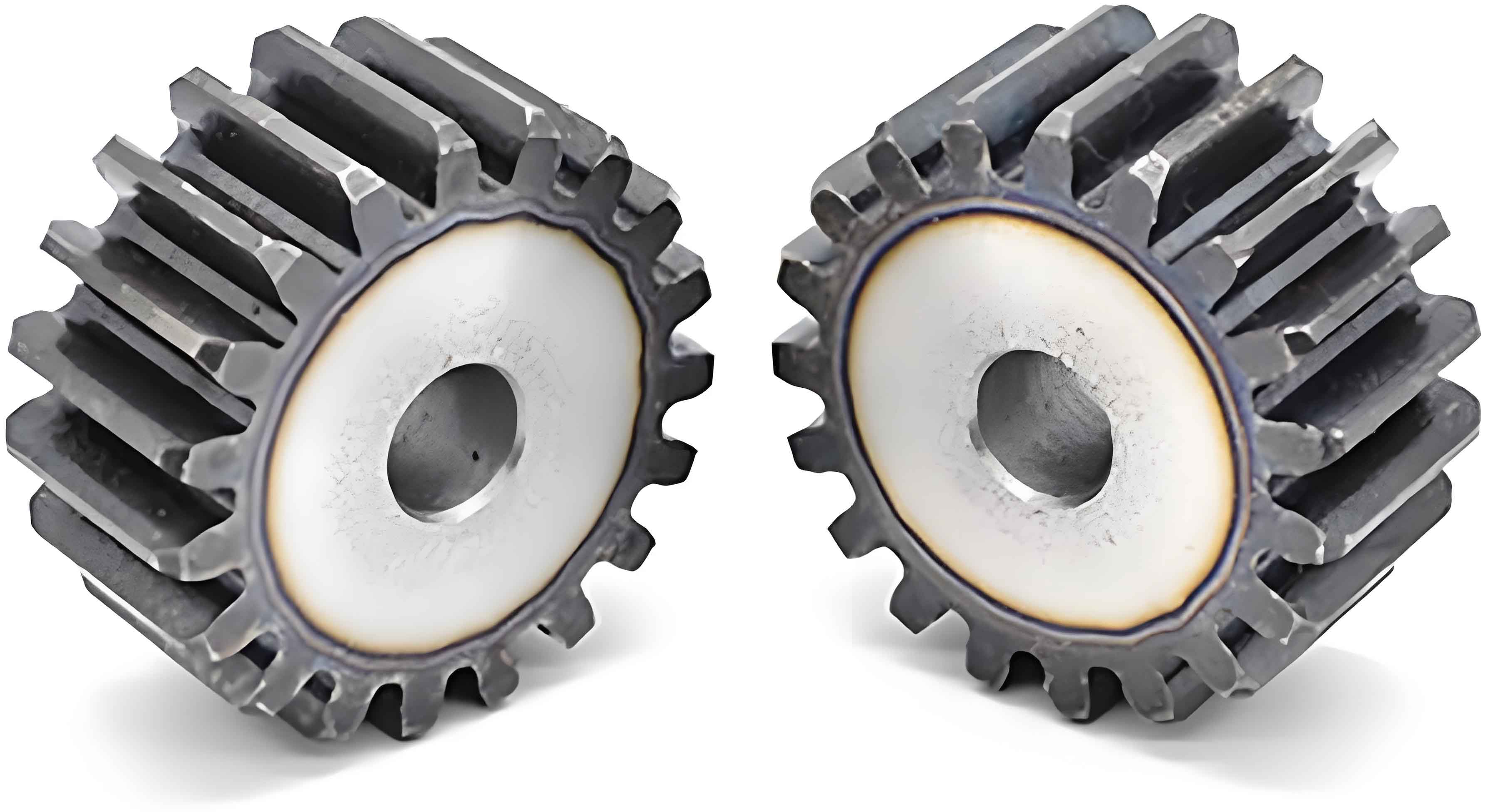
3.1 Design of Staggered Phase Tuning Scheme
To verify the vibration reduction effect of staggered phases and minimize errors introduced by processing and assembly, a spline connection is used in the experiment. Three staggered phase angles are selected for experimental investigation: p = 0, 0.2, 0.4.
<img src=”https://example.com/figure7.png” /> (Note: This is a placeholder image URL, replace it with the actual image URL.)
Table 4: Gear Parameters for Different Test Groups
| Group | Number of Teeth | Module (mm) | Pressure Angle (°) | Tooth Width (mm) | Base Coincidence (ε0) | Ratio Coefficient (λ) |
|---|---|---|---|---|---|---|
| 1 | 16, 17 | 2 | 20 | 40 | 1.506 | 1/2 |
| 2 | 32 | 2 | 20 | 40 | 1.66 | 2/3 |
| 3 | 49 | 2 | 20 | 40 | 1.75 | 3/4 |
3.2 Test Setup and Measurement Points
The test bench parameters are summarized in Table 5.
Table 5: Test Bench Parameters
| Parameter | Value |
|---|---|
| Motor Torque (N·m) | 0~140 |
| Motor Power (kW) | 11 |
| Torque Sensor Range (N·m) | 20/4 |
| Rotational Speed (r/min) | 0~8000 |
| Input End Load (N·m) | 0~20 |
| Output End Load (N·m) | 100/20 |
| Output End Speed (r/min) | 0~2500 |
Vibration displacement measurement points are arranged as shown in Figure 10, and vibration acceleration sensors are used to measure the vibration response in three directions at the input and output ends, as shown in Figure 10.
Table 6: Sensor Parameters
| Sensor Type | Measurement Parameter | Range/Accuracy |
|---|---|---|
| Vibration Displacement Sensor | Displacement | Specified range/high |
| Vibration Acceleration Sensor | Acceleration | Specified range/high |