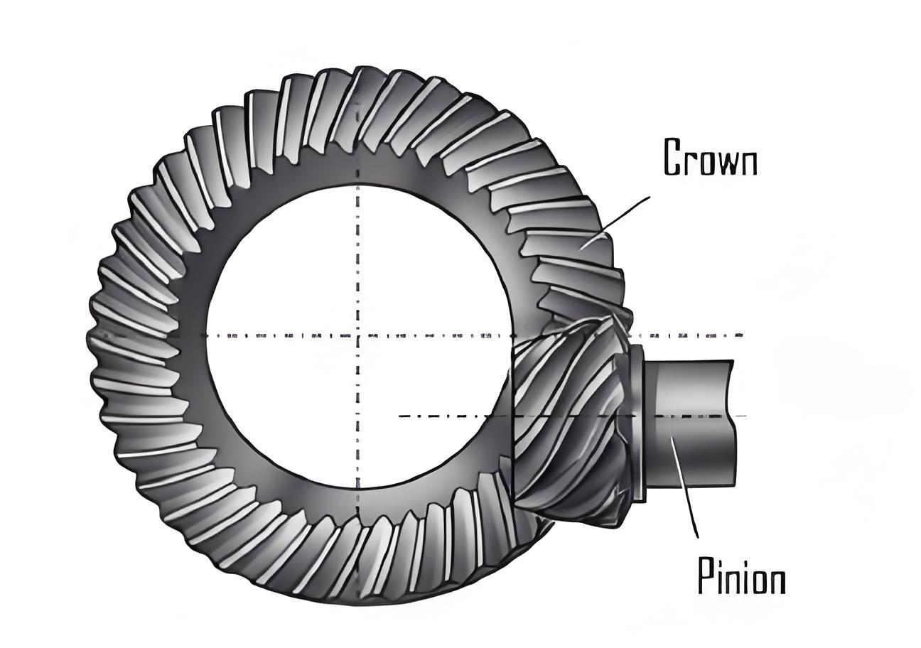
This study presents a vibration reduction optimization method for hypoid gears based on Ease-off flank modification. The method integrates tooth contact analysis (TCA), loaded tooth contact analysis (LTCA), and dynamic modeling to achieve minimized vibration through systematic parameter optimization.
1. Ease-Off Modification Design
The Ease-off surface for pinion modification combines transmission error control and parabolic flank correction. The modified pinion surface is expressed as:
$$ \delta(u,\beta) = (\mathbf{R}_{1\gamma}(u,\beta) – \mathbf{R}_{10}(u,\beta)) \cdot \mathbf{N}_{10}(u,\beta) $$
where $u$ and $\beta$ represent surface parameters, $\mathbf{R}$ denotes position vectors, and $\mathbf{N}$ indicates normal vectors. The modification parameters include:
| Modification Type | Parameters | Range |
|---|---|---|
| Tooth Space Clearance | $\epsilon_0-\epsilon_4$, $\lambda_1-\lambda_2$ | $-12.3”$ to $0.61$ rad |
| Flank Normal Clearance | $d_1-d_2$, $q_1-q_2$, $\theta_a$ | $1.73-2.03$ mm, $0.019-0.022$ mm, $10^\circ$ |

2. Dynamic Modeling
An 8-DOF bending-torsional-axial coupled dynamic model considers time-varying mesh stiffness $K_m(t)$:
$$ \begin{cases}
m_p\ddot{x}_p + c_{px}\dot{x}_p + k_{px}x_p = -F_nn_{px} \\
I_p\ddot{\theta}_p = -F_nr_p + T_p \\
m_g\ddot{x}_g + c_{gx}\dot{x}_g + k_{gx}x_g = -F_nn_{gx} \\
I_g\ddot{\theta}_g = F_nr_g – T_g
\end{cases} $$
where $F_n$ represents dynamic meshing force:
$$ F_n = K_m(t)\left[ \delta_n – e_n(t) \right] + C_m\dot{\delta}_n $$
3. Optimization Framework
The vibration reduction optimization uses particle swarm algorithm with objectives:
$$ \text{Minimize } G(\mathbf{y}) = \frac{RMS(a_{modified})}{RMS(a_{nominal})} $$
Key parameters influencing hypoid gear dynamics:
| Parameter | Pinion | Gear |
|---|---|---|
| Number of Teeth | 8 | 41 |
| Module (mm) | 5.77 | 1.05 |
| Spiral Angle (°) | 48.93 | 30.63 |
| Support Stiffness (N/m) | $5\times10^8$ | $5\times10^8$ |
4. Results Analysis
Optimized Ease-off modification demonstrates significant vibration reduction:
| Modification Case | ALTE (%) | Vibration Reduction (%) |
|---|---|---|
| Nominal | 100 | 0 |
| Optimal Ease-off | 65 | 85 |
| Over-modified | 49 | 4 |
The mesh stiffness spectrum shows:
$$ K_m(f) = K_{avg} + \sum_{n=1}^\infty A_n\cos(2\pi nf_m t + \phi_n) $$
where optimal modification reduces higher harmonics ($A_3/A_1 < 0.2$) compared to nominal design ($A_3/A_1 > 0.5$).
5. Dynamic Response Characteristics
Critical speed analysis reveals resonance shifts:
$$ f_{critical} = \frac{1}{2\pi}\sqrt{\frac{K_m}{m_{eq}}} $$
where equivalent mass $m_{eq}$ for hypoid gear pairs is calculated as:
$$ m_{eq} = \frac{I_pI_g}{r_p^2I_g + r_g^2I_p} $$
| Condition | Resonance Speed (rpm) | Dynamic Force (N) |
|---|---|---|
| Nominal | 5,600 | 1,250 |
| Optimal | 8,000 | 680 |
6. Load-Dependent Behavior
The relationship between ALTE and vibration under varying loads follows:
$$ \frac{RMS(a)}{RMS(a_0)} = 0.85\left(\frac{T}{T_0}\right)^{0.6} + 0.15 $$
demonstrating improved load capacity of modified hypoid gears.
7. Conclusion
This systematic approach for hypoid gear optimization achieves 85% vibration reduction through Ease-off modification, demonstrating that stiffness curve shaping is more critical than absolute stiffness reduction. The method enables balanced performance in load capacity and dynamic behavior for automotive driveline applications.
