
In the field of industrial robotics, the precision and stability of motion are paramount, and at the heart of this lies the performance of the reducer. Among the various types available, the RV reducer, short for Rotary Vector reducer, has emerged as a critical component due to its high transmission ratio, substantial load capacity, and compact structure. As a researcher focused on mechanical transmission systems, I have dedicated significant effort to understanding and optimizing the RV reducer. The complexity of its design, particularly the interaction between the cycloidal gear and the pin teeth, poses challenges for traditional theoretical analysis. To address this, I embarked on a project to construct a virtual prototype of an RV reducer, leveraging the synergistic strengths of SolidWorks for detailed three-dimensional modeling and ADAMS for dynamic simulation. This approach not only streamlines the development cycle but also provides profound insights into the operational state of the pin teeth, which are susceptible to wear and fatigue. In this article, I will share my methodology, findings, and the extensive analysis conducted, emphasizing the pivotal role of virtual prototyping in advancing RV reducer technology.
The RV reducer is a two-stage reduction mechanism. The first stage involves a planetary gear train, and the second stage employs a cycloidal-pin gear transmission. This combination allows the RV reducer to achieve high reduction ratios while maintaining robustness. The core of the reduction occurs in the cycloidal stage, where a cycloidal disk, driven via eccentric shafts, meshes with a ring of stationary pin teeth housed in a pin gear casing. The motion is then output through the pin gear casing or related components. Understanding the dynamics of this meshing is essential for enhancing the longevity and accuracy of the RV reducer.
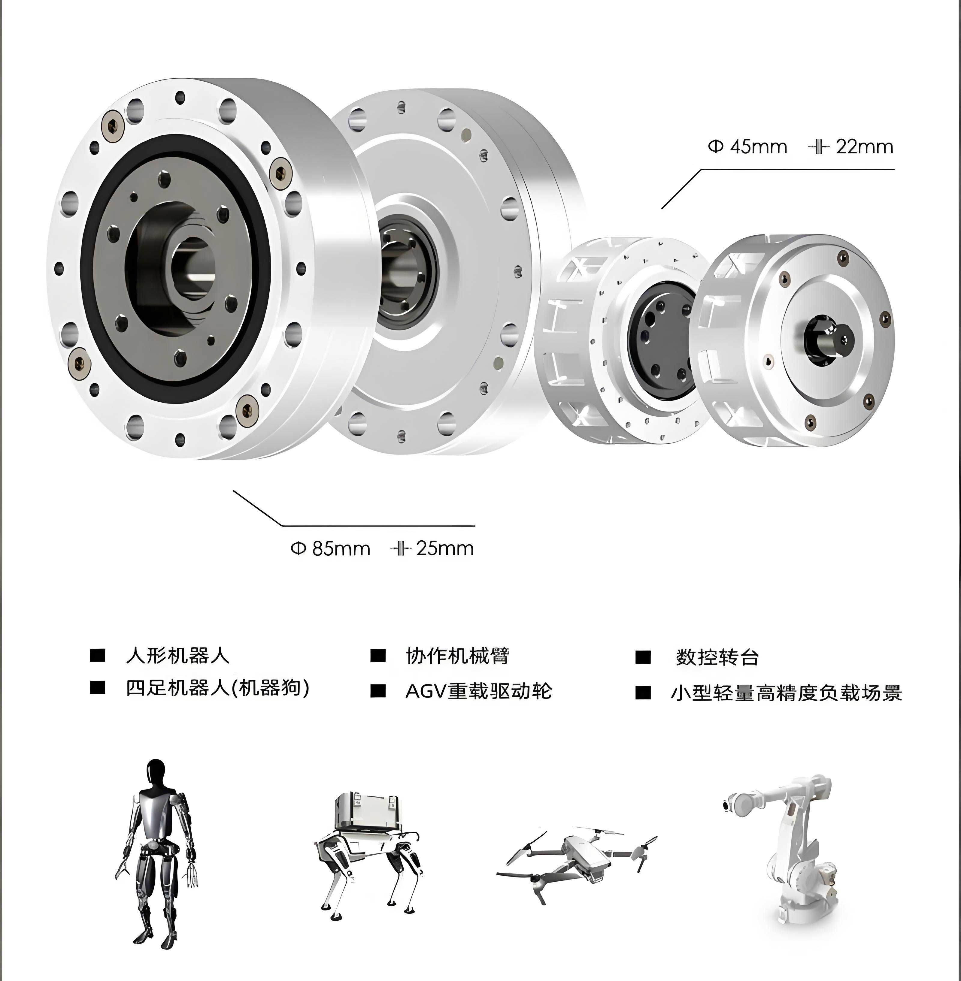
My journey began with creating an accurate three-dimensional model. I chose SolidWorks for its superior capability in handling complex geometries, especially the profiled curve of the cycloidal disk. The standard equation for a cycloidal curve is given by:
$$x = r_p \left( \sin\left(\frac{\theta}{Z_c}\right) – \frac{K_1}{Z_p} \sin\left(\frac{Z_p}{Z_c} \theta\right) \right)$$
$$y = r_p \left( \cos\left(\frac{\theta}{Z_c}\right) – \frac{K_1}{Z_p} \cos\left(\frac{Z_p}{Z_c} \theta\right) \right)$$
where \( r_p \) is the radius of the pin center circle, \( Z_c \) is the number of teeth on the cycloidal disk, \( Z_p \) is the number of teeth on the pin gear (theoretical), and \( K_1 \) is the cycloidal shortening coefficient, defined as \( K_1 = \frac{e Z_p}{r_p} \), with \( e \) being the eccentricity. For the specific RV reducer I studied, the fundamental parameters are summarized in Table 1.
| Parameter | Symbol | Value | Unit |
|---|---|---|---|
| Base Circle Radius | \( r_p \) | 188 | mm |
| Number of Cycloidal Teeth | \( Z_c \) | 59 | – |
| Pin Tooth Radius | \( r \) | 4.9 | mm |
| Shortening Coefficient | \( K_1 \) | 0.6383 | – |
| Eccentricity | \( e \) | 2 | mm |
However, in practice, to optimize performance and reduce vibration, the cycloidal disk is often modified. I applied a negative equidistant modification method with a modification amount \( \Delta r_p = 0.008 \, \text{mm} \). The modified equation becomes:
$$x = (r_p – \Delta r_p) \left( \sin\left(\frac{\theta}{Z_c}\right) – \frac{K_1}{Z_p} \sin\left(\frac{Z_p}{Z_c} \theta\right) \right)$$
$$y = (r_p – \Delta r_p) \left( \cos\left(\frac{\theta}{Z_c}\right) – \frac{K_1}{Z_p} \cos\left(\frac{Z_p}{Z_c} \theta\right) \right)$$
For the working range, I set \( \theta \) from \( \pi \) to \( 3\pi \). Using parametric equation-driven curves in SolidWorks, I generated the cycloidal profile and proceeded to model all components, including the planetary gears, eccentric shafts, pin teeth, housing, and support plates. The assembly was meticulously checked for interferences and kinematic correctness in UG software to ensure it reflected the real-world operation of the RV reducer. This step was crucial before transitioning to dynamic simulation.
With the 3D model validated, the next phase involved building the virtual prototype in ADAMS. To enhance simulation efficiency and stability, I simplified the model by removing non-essential features. Small components like bearings, washers, seals, bolts, and pins were omitted. Instead, I utilized built-in modules from ADAMS, such as bearing elements, to represent their functions. Fillet and chamfer features were suppressed, and fastening connections were replaced with appropriate joints. The simplified model was exported in Parasolid (.x_t) format and imported into ADAMS. The environment was configured with standard gravity (9.81 m/s²), and units were set to MMKS (mm, kg, N, s). Materials were assigned to each part, defining properties like density, Young’s modulus, and Poisson’s ratio typical for alloy steels.
Defining constraints and joints is the backbone of a functional virtual prototype. I established the following kinematic pairs and contacts to replicate the actual mechanics of the RV reducer:
- Fixed Joints: These were used to immovably connect the pin gear casing to the ground (representing the fixed frame), the support plate to the planet carrier, and each eccentric shaft to its corresponding planetary gear.
- Revolute Joints: Revolute joints were applied to allow rotation: each pin tooth about its own axis in the casing, each eccentric shaft relative to the planet carrier, each planetary gear relative to the support plate, the planet carrier and support plate relative to the ground, and the sun gear relative to the ground.
- Bearing Elements: The six eccentric sections on the three shafts interacting with the two cycloidal disks were modeled using ADAMS’s built-in bearing force elements. This simplified representation captures the radial support without the complexity of detailed bearing geometry.
- Contact Forces: Critical interactions were defined using contact forces. Contacts were established between all 30 pin teeth and both cycloidal disks, and between the sun gear and the three planetary gears. Using contact instead of idealized gear joints accounts for impact, friction, and deformation, providing a more realistic simulation of meshing dynamics. The contact parameters were set based on steel-on-steel interaction with appropriate stiffness and damping.
The drive system was modeled to match real operational conditions. In this RV reducer configuration, the planet carrier and support plate are fixed, the sun gear is the input, and the pin gear casing is the output. The maximum motor speed is 4300 rpm, but after an initial bevel gear reduction (not modeled in detail here), the input to the sun gear is approximately 1400 rpm, or 8400 deg/s. To simulate a realistic start-up, I applied a step function drive to the sun gear’s revolute joint:
$$\text{Drive}(t) = \text{step}(time, 0, 0, 5, 8400) \times 1d + \text{step}(time, 5, 0, 10, 0) \times 1d$$
This function ramps the speed from 0 to 8400 deg/s over 5 seconds, holds it for 5 seconds, and then ramps down to 0. Additionally, to study force distribution under load, a preload torque of 3700 N·m was applied to the pin gear casing output, simulating resistance.
The constructed virtual prototype of the RV reducer was then subjected to dynamic simulation over a 10-second period. The primary objective was to verify kinematic accuracy and then delve into the force analysis of the pin teeth. The transmission ratio for this fixed-carrier, sun-input, casing-output RV reducer is given by:
$$i = \frac{1}{1 – R}$$
where \( R = 1 + \frac{Z_2}{Z_1} \cdot \frac{Z_4}{Z_3} \). Here, \( Z_1 \) is the sun gear teeth (input), \( Z_2 \) is the planetary gear teeth, \( Z_3 \) is the cycloidal disk teeth (\( Z_c \)), and \( Z_4 \) is the theoretical pin teeth number (\( Z_p \)). With the actual pin teeth number halved to 30 for reduced vibration, the effective meshing changes, but the theoretical ratio provides a baseline. From simulation, I measured the angular velocities of the sun gear, a planetary gear, and the pin gear casing. The curves showed expected trends: the sun gear speed followed the step input, the planetary gear exhibited a compounded rotation, and the casing output speed was significantly reduced. The simulated reduction ratio closely matched the theoretical calculation, with minor deviations due to dynamic effects and contact compliance, validating the virtual prototype’s fidelity.
The most insightful analysis pertained to the state of the pin teeth. Given their critical role and high susceptibility to fatigue, understanding their load history is vital for the RV reducer’s durability. I instrumented every pin tooth to measure the contact force magnitude over time. A representative force curve for one pin tooth is shown in Figure 1 (note: the figure is a conceptual representation based on simulation data). The force exhibits a highly periodic pattern with rapid fluctuations. Even though the peak-to-peak force variation is not extremely large, the frequency of loading cycles is very high. This implies that each pin tooth undergoes millions of stress cycles in a short operational period, a classic scenario for fatigue initiation. Furthermore, by examining force plots for all 30 pin teeth simultaneously, I observed that at any given instant, precisely 10 pin teeth (5 in contact with the upper cycloidal disk and 5 with the lower) are actively engaged in transmitting torque. This load-sharing characteristic is crucial; it distributes the forces but also means a subset of pins consistently bears the brunt of the load during operation. The force distribution among these active pins was relatively uniform, but slight variations existed due to the modified cycloidal profile and assembly tolerances.
To quantify the dynamic performance, I compiled key simulation results in Table 2. This includes average speeds, peak forces, and observed frequencies, which are instrumental for design validation and comparison with theoretical models.
| Metric | Simulated Value | Theoretical Value | Notes |
|---|---|---|---|
| Sun Gear Max Speed | ~8400 deg/s | 8400 deg/s | Matches input drive |
| Pin Gear Casing Output Speed (Avg) | ~5.72 deg/s | 5.71 deg/s | Corresponds to i ≈ 1470 |
| Planetary Gear Speed Amplitude | ~2800 deg/s | Calculated based on kinematics | Consistent with stage 1 reduction |
| Peak Pin Tooth Contact Force | ~450 N | Est. from torque divide | Depends on load and position |
| Pin Tooth Load Cycle Frequency | ~500 Hz | Function of input speed and teeth count | High cycle fatigue regime |
| Number of Simultaneously Loaded Pins | 10 | Theory predicts ~Z_c/π | Validates load distribution model |
The construction and analysis of this virtual prototype for the RV reducer have yielded significant advantages over purely theoretical approaches. First, the integration of SolidWorks and ADAMS proved highly efficient, allowing rapid iteration from design to dynamic assessment. Second, replacing intricate components with simplified ADAMS elements accelerated simulation without compromising essential physics. Most importantly, the virtual prototype enabled a deep dive into the transient dynamics of the pin teeth—something extremely tedious to compute analytically, especially after cycloidal modification. The insights into the periodic, high-frequency loading and the precise number of concurrently engaged pin teeth provide actionable data for material selection, heat treatment specifications, and lubrication design for the RV reducer. For instance, knowing the load frequency aids in designing fatigue tests, and understanding the load-sharing pattern can guide tolerance stacking and alignment procedures during manufacturing.
In conclusion, the virtual prototyping methodology presented here is a powerful tool for the development and optimization of RV reducers. It bridges the gap between theoretical design and physical testing, reducing development time and cost. The RV reducer, with its complex kinematics, benefits immensely from such simulation-led analysis. Future work could involve incorporating flexible body dynamics to study structural deformations, thermal effects on lubrication, or exploring different modification profiles for the cycloidal disk to further optimize the stress distribution on the pin teeth. The continual advancement in simulation technology promises even greater fidelity in virtual prototyping, solidifying its role as an indispensable asset in perfecting the performance and reliability of critical components like the RV reducer in robotic systems.
Throughout this exploration, the term RV reducer has been central, underscoring its importance in robotics transmission. The ability to model and simulate its behavior virtually marks a significant step forward in engineering practice. As demands for higher precision and durability in robots grow, so too will the reliance on sophisticated virtual prototyping techniques to unlock the full potential of the RV reducer.