
The pixel size of the image was measured using the standard 6 × 9 checkerboards, each with a size of 6 mm × 6 mm, use Harris corner detection algorithm to detect corners, and find the actual size represented by each pixel according to the coordinates of the corners. In this paper, one pixel represents 0.024 1 mm.
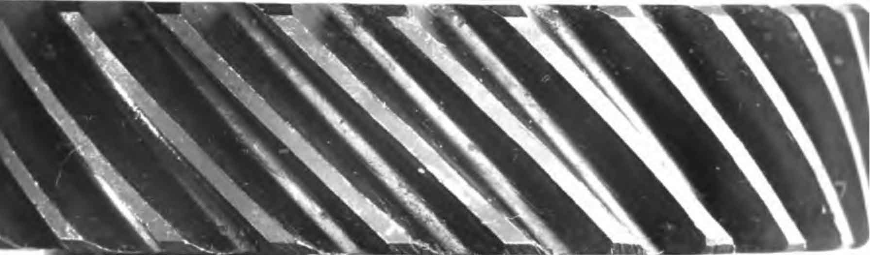
Based on matlab2020a platform, Zhang’s calibration method is used to calibrate the camera first, and then distortion correction, ROI extraction, graying and other operations are performed on the image. As shown in the figure, in the large-scale industrial vision measurement of helical gears, the workpiece uses an automatic baffle to make the workpiece stationary in a fixed area. After the image is collected, the baffle will release the workpiece. Then, the abscissa of the ROI area of the figure is only related to the diameter of the addendum circle. When measuring helical gears with unknown parameters, the top camera measures the diameter of the addendum circle, the number of teeth, the diameter of the graduation circle and other parameters of the helical gear end face. Without these parameters, it is impossible to fit the extracted tooth line edges. Since the pitch circle diameter of helical gears is generally negative tolerance, measuring the actual pitch circle diameter with the top camera is helpful to reduce the error of the proposed method and to automatically obtain the coordinates of the ROI area. The ROI image of helical gear after distortion correction is shown in the figure.
Due to the limited experimental conditions, it is difficult to ensure that the workpiece image does not tilt. Therefore, it is necessary to measure the inclination angle of the workpiece to match the image coordinate system with the world coordinate system, fix the helical gear with the shaft, and obtain a more accurate inclination angle through the image of the shaft. The ROI image of the shaft is extracted from the image. After edge extraction, the analytical formula of the inclination angle of the shaft and the center line of the helical gear is obtained by least square fitting. Combined with the coordinates of the ROI area, the position of the origin of the image coordinate system is obtained.