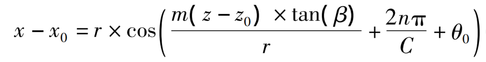
Helical cylindrical gear is referred to as helical gear for short. The tooth line of helical gear is the combination of a series of helices on the side of the same cylinder. The parametric equation of the helix in the space Cartesian coordinate system is as follows:
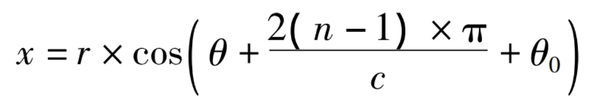
Where: C – number of teeth of helical gear; N-an arithmetic sequence with an interval of 1 from 1 to C; θ— Angle parameter, range (- B / 2R, 0) radian.
Where: when n is 1, the angle between the line connecting the starting point and the origin of the first helix and the X axis is θ 0
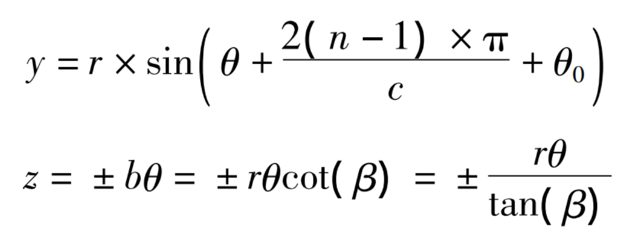
Where: β— Helical angle of helical gear; Z-vertical coordinate, range [0, b]; B – thickness of helical gear (height of helix in Z direction).
In the end face coordinate system, the rotation angle of the helix corresponding to each tooth is (2 π / C) radians. In formula (3), when the sign of R and B is negative, the helical gear is left-handed, otherwise it is right-handed.
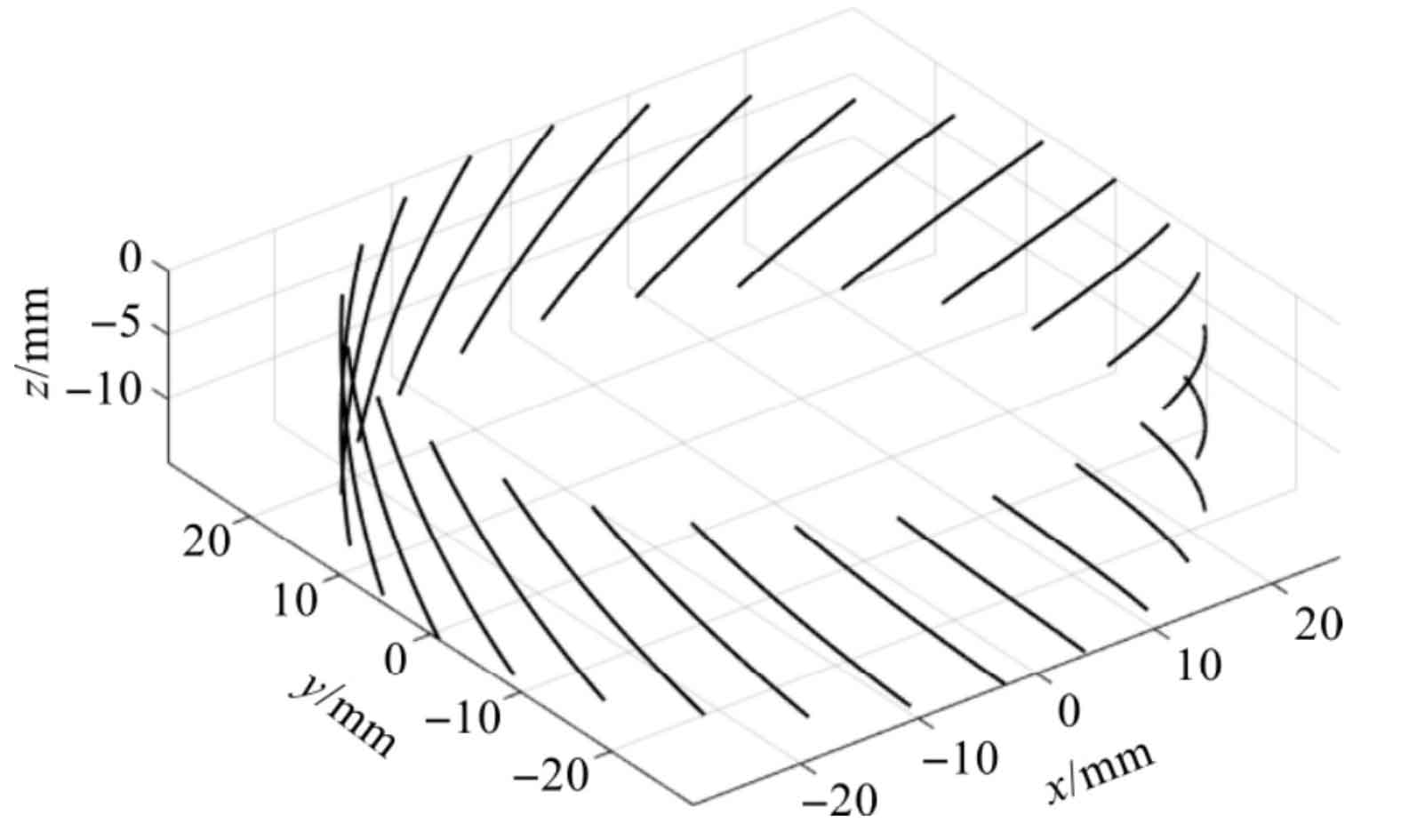
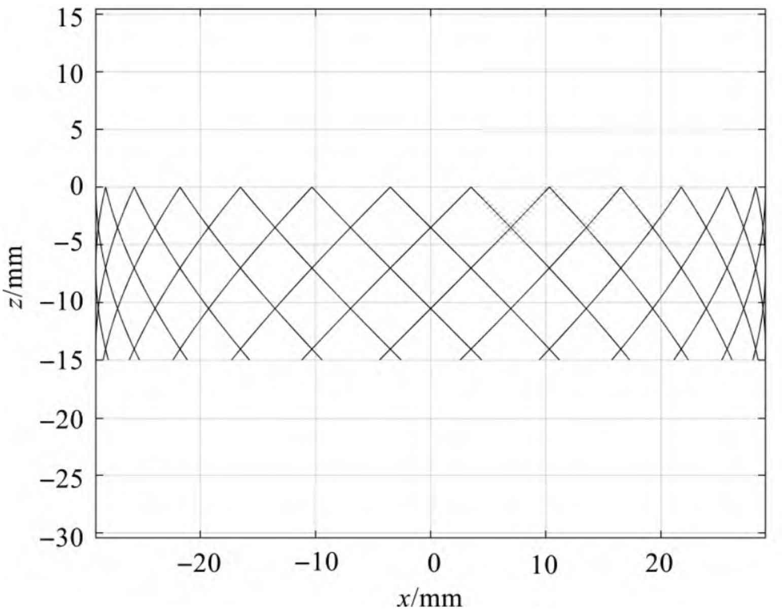
Taking a 45 ° helical gear with a thickness of 15 mm and a modulus of 26 teeth of 1.5 as an example, the helical gear tooth profile can be obtained by substituting the formula into the parameters and inputting it into Matlab, as shown in Fig. 1.
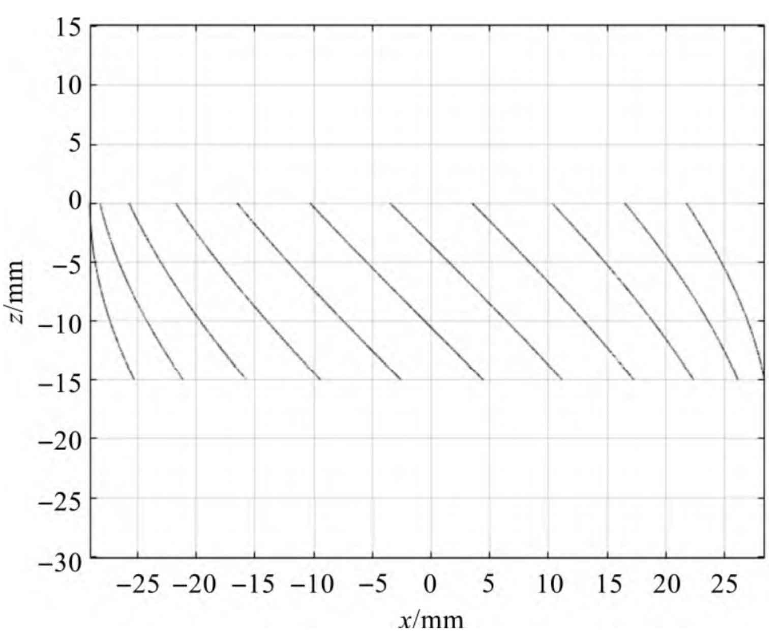
It can be seen from the projection image Fig. 2 that all projections of the tooth line on the xoz plane are not straight lines, but the projection of the tooth line in the middle is similar to the straight line. Since the camera can only capture the image in front of the helical gear, the tooth profile curve at the Y > 0 part is invisible, so (0 < 2 (n-1) π / C+ θ 0 < π) 。
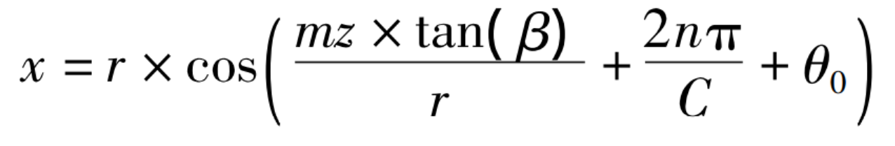
Only the tooth profile part of the image that can be acquired by the camera is considered, and the projection of part of the tooth profile curve on the xoz plane is shown in Fig. 3.
The function expression of X and Z can be obtained by simultaneous formula (1, 3):
Other parameters remain unchanged and change within [0: 0.05: 1] radians β The resulting image is shown in Fig. 4.
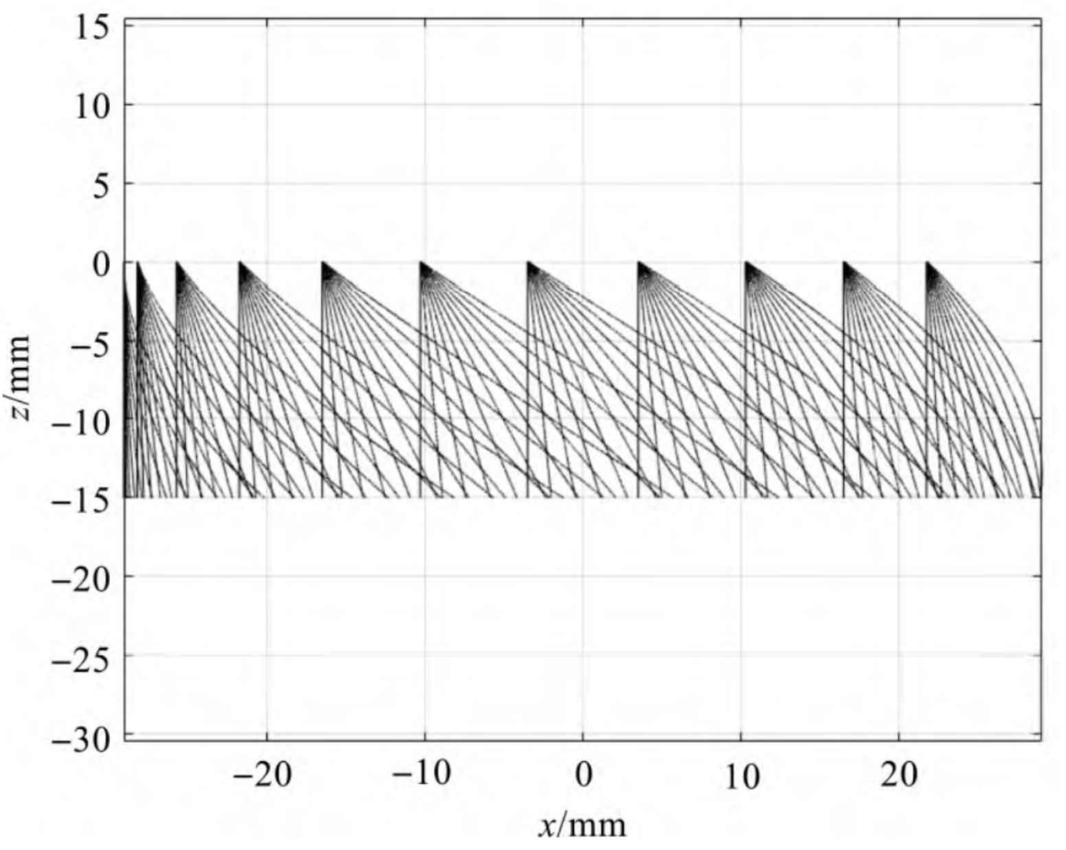
As can be seen from Fig. 4: β When the size of is within a certain range, the projection curve is unique.
When the intersection of the axis of the cylindrical helical gear and the upper end face is (x0, Z0), the functional expression of X and Z is:
Compared with the method of directly using the connecting line of the lower end of the intermediate gear line, when the coordinate of the upper vertex of the gear line of the 1.5 module 26 tooth 45 ° helical gear image is (- 39.78,0), the error is theoretically 0.91% more than that of the algorithm. In an ideal case, the error of the algorithm only depends on the resolution of the camera and the error of the parameters such as the diameter of the tooth crest circle measured by end face vision.
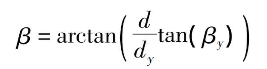
For standard helical gears, the diameter of the addendum circle is generally equal to the diameter of the graduation circle plus twice the module of the helical gear. The conversion relationship between the helix angle of the addendum circle and the helix angle of the indexing circle can be expressed as the following two equations:
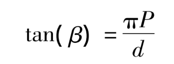
Where: P – helix lead (unchanged); D – graduation circle diameter.
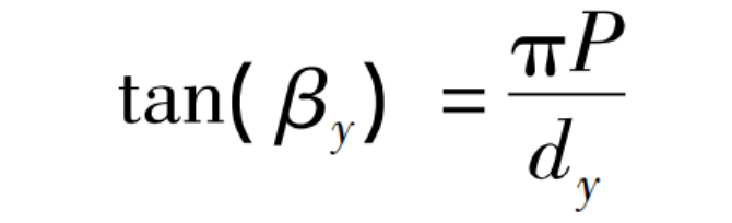
Where: β Y-helix angle of tooth crest circle; Dy – diameter of tooth crest circle.
The helix angle of degree circle can be obtained by the formula: β, Namely: