
1. Basic wear model
In the meshing process of gear pair, the relative sliding and rolling occurs between the meshing tooth surfaces, which causes wear between the meshing tooth surfaces. For any meshing point, using the generalized Archard wear formula, the wear amount can be expressed as:

Where h is the wear depth at the meshing point, s is the relative slip distance, K is the dimensional wear coefficient, and P is the Hertz contact pressure.
By integrating the above formula on the relative slip distance, the wear depth of any meshing point P on the tooth profile is obtained as follows:

Where: HWP is the wear depth at point P, kW is the wear coefficient and SP is the wear coefficient
The sliding distance of point P, PP is the contact pressure at point P. Based on the single point observation method, after the nth + 1st meshing cycle, the wear at any meshing point P in the meshing tooth surface can be expressed as:

2. Contact pressure

For involute spur gear, its meshing contact is usually equivalent to cylindrical roller contact with variable radius. As shown in Figure 1, the radius of two cylindrical rollers is equal to the radius of involute curvature, that is, the distance from the contact point to the upper tangent point of the base circle

Where, d0i = (I = 1,2) is the pitch circle diameter of the gear, A0 is the pressure angle, AP is the center angle corresponding to the meshing point, and Y is the distance from the meshing point to the node, i.e., y = RB1 (tanap-tana0). According to Hertz contact theory, the equivalent radius of curvature at any meshing point P can be expressed as:

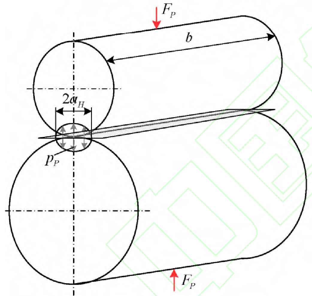
Due to the action of normal meshing force, the tooth has local elastic deformation on the meshing contact surface, and the contact area as shown in Fig. 2 is formed on the contact surface. Based on Hertz contact theory, the contact half width and contact pressure at the meshing point P can be expressed as:

Where FP is the normal meshing force, B is the meshing tooth width, and E * is the equivalent elastic modulus

Where E1 and E2 are the elastic modulus of the two gears respectively, and V1 and V2 are the Poisson’s ratio of the two gears respectively.
3. Relative sliding distance
The relative sliding distance of P1 and P2 on the tooth profiles of driving and driven gears corresponding to the contact point is as follows:

Where, U1 and U2 represent the circumferential speeds of P1 and P2 on the tooth profiles of the driving and driven gears, respectively

4. Dynamic wear coefficient
In fact, the wear coefficient is related to material properties, operating conditions, surface roughness and lubrication conditions. Considering the influence of oil film thickness, priest and Taylor proposed an approximate dynamic wear coefficient model

Where, λ It is defined as the minimum oil film thickness (Hmin) and the root mean square (RA) of the surface roughness of the driving and driven gears_ The ratio of RMS, when λ< At 0.5, the master-slave gear face is in the boundary lubrication state, the lubrication condition is poor, and the wear coefficient is the largest; When 0.5 ≤ λ When the wear coefficient is less than or equal to 4, the tooth surface of the driving and driven gears is in the mixed lubrication state λ It is linear; And when λ> The results show that the master-slave gear surfaces are in elastohydrodynamic lubrication state, the lubrication condition is good, and the wear coefficient is close to 0.

The minimum oil film thickness between the meshing surfaces of the driving and driven gears can be expressed as:

Where, σ Is the ellipticity parameter (for the contact problem of involute spur gear, it can be assumed to be infinite), UW, GW and LW are dimensionless velocity, dimensionless material parameter and dimensionless load, respectively

Where, η 0 is the absolute viscosity at the reference ambient pressure, and E’is the equivalent modulus of elasticity e’ =2e’, α Is the viscosity pressure coefficient of lubricating oil, μ Is the rolling speed of the contact point μ=( U1 + U2) / 2, for the low speed condition, the dimensionless speed is very small, the oil film thickness can be approximately zero, far less than the root mean square of gear surface roughness, so the gear runs in the boundary lubrication state.
Janakiraman et al. Considered the influence of the above factors on the wear coefficient and used the statistical analysis method to give the fitting wear coefficient

Where SW is the root mean square of the dimensionless composite surface roughness, which can be expressed as SW = RA_ rms/ ρ 。