
Figure 1 shows the pressure cloud diagram of the driven gear tooth surface. The pressure P is in MPa. It can be seen from Figure 1 that the spiral bevel gear with all configurations has a maximum pressure on the gear teeth that will enter the meshing state. However, the pressure on the tooth surface of the gear that is about to leave the meshing state is low. Because the meshing area of the spiral bevel gear is point meshing, the possible reason for this situation is that the air in the tooth groove is squeezed during the process of the gear teeth gradually entering the meshing area, resulting in a large air pressure here. Therefore, a maximum pressure value appears on the gear teeth that are about to enter the meshing state on the spiral bevel gear; The minimum value of the pressure on the tooth surface of the gear teeth that are about to leave the meshing state is due to the pressure difference between the space originally occupied by the gear teeth and the ambient pressure when the two meshing gear teeth leave. The above discussion is also valid for the driving wheel.
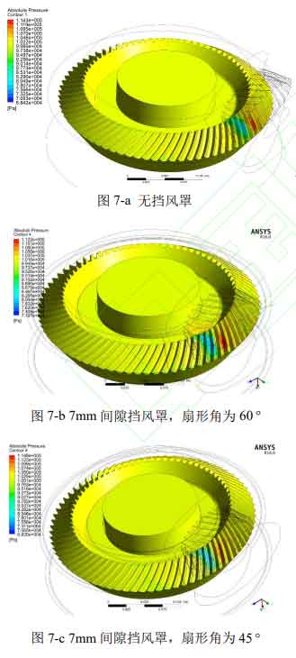
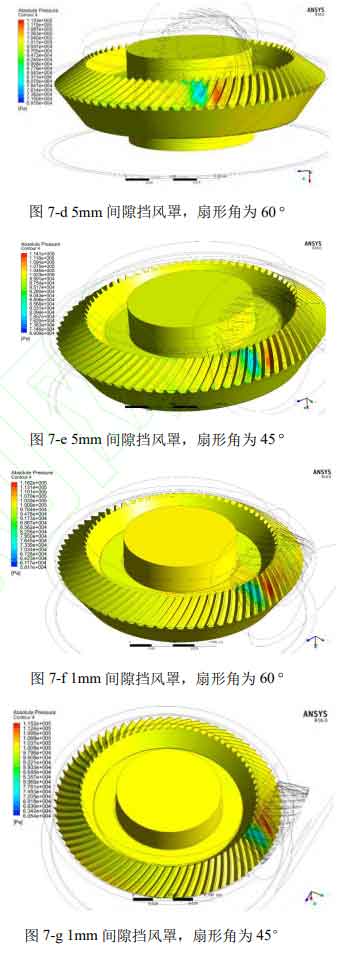
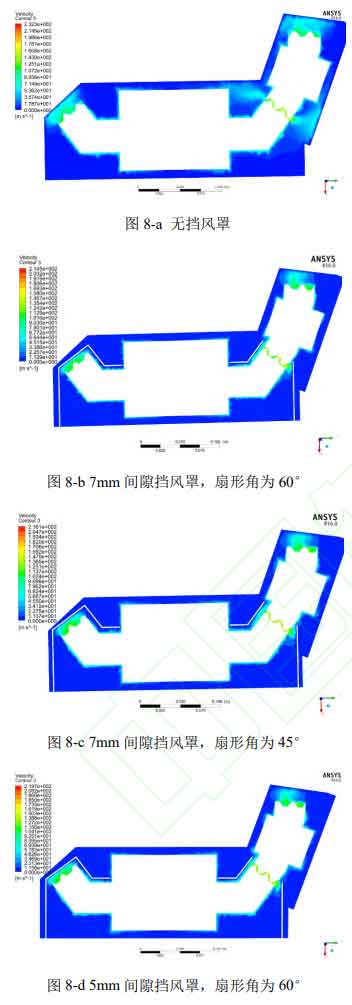
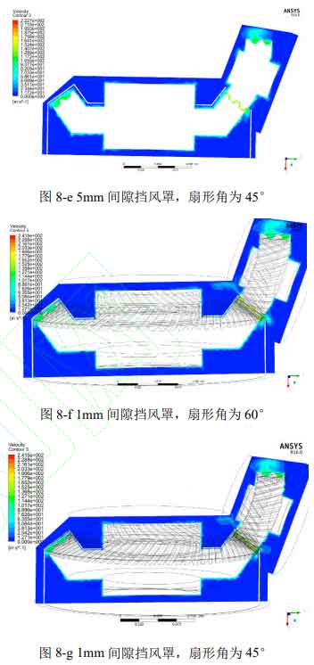
Figure 2 shows the velocity nephogram of X-Y profile, with velocity v in m/s. It can be seen from Figure 2 that the air velocity in the fluid zone between the wind shield and the box body decreases significantly after the installation of the wind shield. As the gap between the wind shield and the spiral bevel gear shrinks, the peak velocity of air in the flow field between the wind shield and the spiral bevel gear increases, but the flow field area with higher velocity decreases.
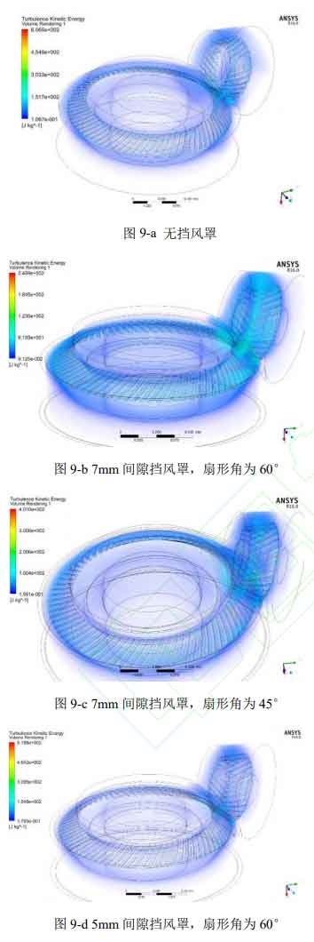
The turbulent flow energy cloud diagram of the flow field shown in Figure 3, the turbulent kinetic energy k unit J, can be seen from Figure 3 that the average turbulent kinetic energy of the flow field with a clearance of 7mm of the wind shield is greater than that without the wind shield, and the size of the turbulent kinetic energy reflects the severity of the flow field turbulence, and the greater the value is, the greater the wind resistance loss will be. Therefore, the above reflects that the excessive clearance between the wind shield and the spiral bevel gear may have a negative effect on reducing the wind resistance loss, As the clearance between the wind shield and the spiral bevel gear decreases, the average turbulent flow energy of the flow field near the gear tooth surface decreases. Compared with b and c or d and e in Figure 3, it can be seen that the opening and closing angle of the wind shield has no significant impact on the turbulent kinetic energy. At the same time, regardless of the configuration, the turbulent kinetic energy near the meshing area is the largest in the whole flow field, which is caused by the complex boundary movement and energy exchange in the meshing area.
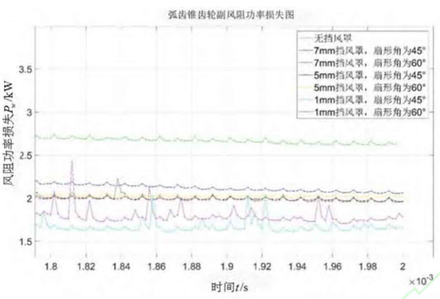
The existing research data show that the wind shield with the best effect under the operation of a single gear can reduce the wind resistance power loss of spiral bevel gears by 70%~75%. The wind shield with the best effect in the simulation (the wind shield configuration corresponding to the No. 6 simulation) can reduce the wind resistance power loss of the spiral bevel gear by 55.3%. At this time, the gap between the wind shield and the spiral bevel gear is 1mm. From the perspective of actual installation, it is impossible to reduce the wind resistance loss by reducing the distance between the wind shield and the spiral bevel gear. As shown in Figure 4, the wind resistance of the spiral bevel gear changes with time. The wind resistance is the minimum when the gap between the wind shield is 1mm and the opening is 45 degrees, Therefore, No. 6 wind shield is configured as a local optimal wind shield. The actual wind resistance of spiral bevel gear pair may be different from the simulation results. One reason is that when there is lubricating oil in the reducer, the flow field medium inside the reducer is actually a two-phase mixture of oil and gas, its density and viscosity are greater than that of air, and the flow field has a relatively high ability to dissipate its own kinetic energy. In the second numerical calculation, air is assumed to be incompressible, while in reality, air is compressible, This will cause the system energy to be consumed by the air compression/expansion in the engagement area. In addition, from the perspective of reducing the volume of the fluid domain directly affected by the driven wheel, there is still considerable space at the bottom of the driven wheel for further reduction, but this involves the design of the whole reducer.
For the actual wind resistance power loss of spiral bevel gear, in addition to the influence of lubricating oil, it should also consider the case that the main reducer is not sealed. When the main reducer is connected with the outside world (other parts or atmosphere), the fluid in the main reducer can exchange mass and energy with the outside world, which means that the fluid mass involved in dissipating the kinetic energy of the fluid in the reducer increases, so the wind resistance power loss of spiral bevel gear will be greater.