
According to the law of conservation of energy, the algebraic sum of the input and output power of the three elements should be equal to zero, thus the characteristic equation of the general motion law of the single row planetary gear mechanism is obtained.
Characteristic equation: N1 + an2 – (1 + a) N3 = 0
N1 — speed of sun gear, N2 — speed of ring gear, N3 — speed of planet carrier, a — ratio of number of teeth between ring gear and sun gear.
From the characteristic equation, it can be seen that the single row planetary gear mechanism has two degrees of freedom. Among the three mechanisms, the sun wheel, the ring inner ring gear and the planet carrier, two of them are selected as the driving and driven parts respectively, so that the other component is fixed, or its movement is constrained to a certain extent (that is, the rotational speed of the component is a certain fixed value), then the mechanism has only one degree of freedom, and the whole gear system Transmit power with a certain transmission ratio. Here are three situations.
1.The ring gear is fixed, the sun wheel is an active part and rotates clockwise, while the star carrier is a passive part. When the sun gear rotates clockwise, the sun gear teeth must give planet gear a a a thrust F1, so the planet gear should rotate counterclockwise, but because the ring gear is fixed, the ring gear teeth must give planet gear B a reaction force F2, and the planet gear must rotate clockwise around the sun gear under the combined force of F1 and F2. As a result, the planet gear not only rotates anticlockwise, but also rotates under the drive of the planet carrier The central axis of the sun wheel rotates clockwise. In this state, the transmission mode of planetary gear mechanism appears, and the rotation direction of the passive part planetary carrier is the same as that of the active part. Here, the sun gear is the driving part and the pinion, and the passive planetary carrier has no specific gear number transmission relationship, so the equivalent number of teeth of the planetary carrier is defined as the sum of the sun gear and the ring gear. In this way, the rotation of the planetary carrier driven by the sun wheel is still the largest gear driven by the pinion, which is a kind of deceleration movement and has the largest transmission ratio. Because N2 = 0 at this time, the transmission ratio i13 = N1 / N3 = 1 + a.
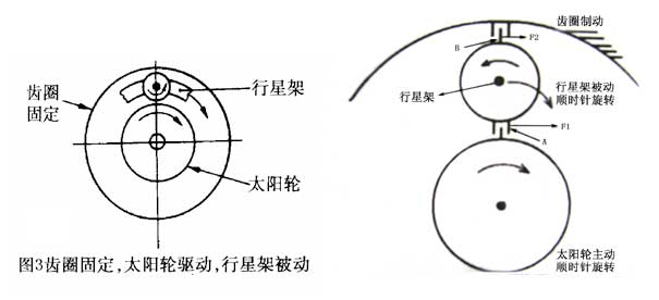
[explain with the wall chart, tell the rotation direction of the components of the planetary gear mechanism through the action and reaction principle of the force, then verify with the single row planetary gear model, and calculate the transmission ratio. ]
2.The sun wheel is fixed, the planet carrier is an active part and rotates clockwise, and the ring gear is a passive part. When the planet carrier rotates clockwise, it will inevitably cause the planet wheel to rotate clockwise. However, due to the sun wheel braking, the sun gear gives a reaction force F1 to the planet gear B, and the planet wheel rotates clockwise under the action of F1. Its gear gives a F2 thrust to the ring gear a, and the ring gear rotates clockwise under the action of F2. Here, the rotation direction of the planetary carrier of the active part is the same as that of the gear ring of the passive part. Because the planet carrier is a gear with the largest equivalent number of teeth, the passive ring gear is output in the way of increasing speed, and the transmission ratio between the two is less than 1. Because N1 = 0 at this time, the transmission ratio i23 = N3 / N2 = A / (1 + a).
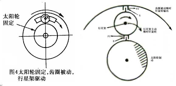
[explain with the wall chart, tell the rotation direction of the components of the planetary gear mechanism through the action and reaction principle of the force, then verify with the single row planetary gear model, and calculate the transmission ratio. ]
3.The planet carrier is fixed, the sun wheel is the driving part and rotates clockwise, while the ring gear is the passive part. Since the planet carrier is fixed, the mechanism belongs to the fixed shaft transmission. The sun wheel rotates clockwise, giving a force F1 to planet gear A, and the planet wheel rotates counterclockwise, giving a force F2 to ring gear B, and the ring gear rotates counterclockwise, as a result, the rotation direction of the ring gear is opposite to that of the sun wheel. In the fixed shaft drive, the planetary wheel plays the role of transition wheel, which changes the rotation direction of the passive gear ring. Because N3 = 0 at this time, the transmission ratio i12 = N1 / N2 = – A.
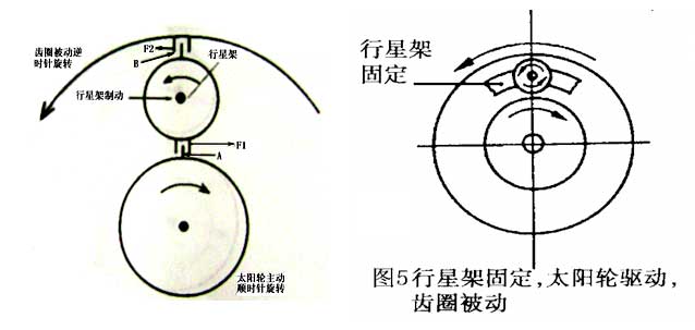
[use the poster to explain, this part uses the interaction method between teachers and students, through the explanation, and then through the single row planetary gear model to verify, and calculate the transmission ratio. ]
4.Interlock any two elements of the planetary gear mechanism. If any two of the sun gear, planet carrier and ring gear of the planetary gear mechanism are interlocked into a whole, there is no relative movement between the gears, and the whole planetary mechanism will become a whole and rotate, which is equivalent to direct transmission. When the sun gear is connected with the ring gear, there will be no relative movement between the teeth of the sun gear and the ring gear, and the planetary gear sandwiched between the sun theory and the ring gear will not be relative movement, so the sun gear, the ring gear and the planet carrier will be integrated, with a transmission ratio of 1.
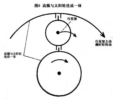
[it is explained with the poster, and the transmission ratio is calculated by the characteristic equation of the general motion law of the single row planetary gear mechanism, and then verified by the single row planetary gear model. ]
5.No components are fixed. If the sun gear, planet carrier and ring gear of the planetary gear mechanism are not fixed, and no two mechanisms are interlocked into one, each component can move freely without any restriction. When the driving part rotates, the driven part can not move, so that it can not transfer power, so as to get neutral.
The output of the ring gear is the problem of increasing or decreasing speed. It can be seen from the structure diagram that the number of teeth of the sun gear is less than the number of teeth of the ring gear, which belongs to the transmission relationship of the pinion driving the big gear. Therefore, the ring gear is obviously in the state of deceleration, that is, the transmission ratio between the two is greater than L. Note that since the planet wheel is a transition wheel, the transmission ratio has nothing to do with the number of teeth of the planet wheel.