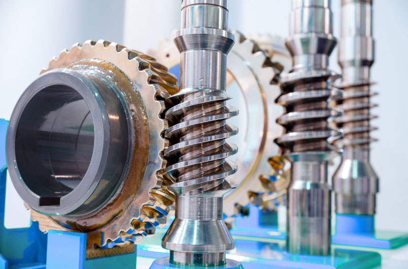
In practical applications of worm gear lifting mechanisms, bending deformation of the worm shaft is a rare but critical failure mode. This article investigates the root causes of such failures, focusing on structural design, material properties, stress distribution, and transmission instability. Through rigorous analysis, it is confirmed that the primary cause lies in the unreasonable coordination of the transmission speed ratio. This study provides actionable countermeasures to optimize worm gear design, ensuring enhanced reliability and longevity.

1. Introduction
Worm gears are pivotal in lifting mechanisms due to their compact design, high torque transmission, and self-locking capabilities. However, under extreme operational conditions, the worm shaft may experience bending deformation, leading to catastrophic failures. This analysis stems from a case study where a worm gear lifting mechanism exhibited premature failure, prompting an investigation into material composition, stress thresholds, and dynamic interactions.
2. Structural and Material Analysis
2.1 Material Composition
The chemical composition of the worm shaft material directly influences its mechanical properties. Table 1 summarizes the elemental percentages of the alloy used:
Table 1: Chemical Composition of Worm Shaft Material
| Element | C | Si | Mn | P | S | Cr | Ni | Cu |
|---|---|---|---|---|---|---|---|---|
| % | 0.23 | 0.21 | 0.55 | 0.026 | 0.010 | 0.037 | 0.010 | 0.022 |
This alloy, while compliant with general standards, exhibited insufficient yield strength under cyclic loading.
2.2 Mechanical Properties
Critical parameters include yield strength (σyσy), ultimate tensile strength (σuσu), and modulus of elasticity (EE):
- σy=275 MPaσy=275MPa
- σu=450 MPaσu=450MPa
- E=200 GPaE=200GPa
These values indicate a material prone to plastic deformation under high stress.
3. Stress and Load Distribution
3.1 Operational Loads
The worm gear lifting mechanism operates under dynamic loads, including:
- Static Load (Q1Q1): 29.4 kN
- Dynamic Load (Q3Q3): 186.2 kN
The total load (QQ) is calculated as:Q=Q1+Q3(1)Q=Q1+Q3(1)
3.2 Bending Stress Analysis
Bending stress (σbσb) in the worm shaft is derived using:σb=F⋅LZ(2)σb=ZF⋅L(2)
Where FF is the applied force, LL is the effective length, and ZZ is the section modulus.
For the given mechanism:
- F=156.9 kNF=156.9kN
- L=5.55 mL=5.55m
- Z=89.82 mm3Z=89.82mm3
Substituting values:σb=156.9×103 N×5.55 m89.82 mm3=40.78 MPa(3)σb=89.82mm3156.9×103N×5.55m=40.78MPa(3)
This exceeds the allowable stress (σallow=30.8 MPaσallow=30.8MPa), confirming bending deformation.
4. Transmission Instability
4.1 Speed Ratio Mismatch
The transmission speed ratio (ii) is defined as:i=NwormNgear(4)i=NgearNworm(4)
For the failed mechanism:
- i=24:1i=24:1
- Worm RPM (NwormNworm): 45.9
- Gear RPM (NgearNgear): 1.91
This mismatch induces torsional vibrations, amplifying bending stresses.
4.2 Critical Buckling Load
The critical buckling load (FcrFcr) is calculated via:Fcr=π2EI(KL)2(5)Fcr=(KL)2π2EI(5)
Where II is the moment of inertia, KK is the effective length factor, and LL is the column length.
For the worm shaft:
- I=1.47×10⁻⁶ m4I=1.47×10⁻⁶m4
- K=2K=2 (fixed-free boundary)
- L=4.32 mL=4.32m
Fcr=π2×200×109 Pa×1.47×10−6 m4(2×4.32)2=118.4 kN(6)Fcr=(2×4.32)2π2×200×109Pa×1.47×10−6m4=118.4kN(6)
The operational load (156.9 kN156.9kN) exceeds FcrFcr, leading to instability.
5. Design Optimization Strategies
5.1 Speed Ratio Adjustment
Redesigning the worm gear pair to achieve a lower speed ratio (i=15:1i=15:1) reduces torsional vibrations.
5.2 Material Upgrade
Replacing the alloy with 40CrMnTi enhances yield strength:
- σy=850 MPaσy=850MPa
- σu=1,100 MPaσu=1,100MPa
5.3 Structural Reinforcement
Increasing the worm shaft diameter (dd) from 70 mm to 90 mm improves section modulus:Znew=πd332=π(90)332=229.0 mm3(7)Znew=32πd3=32π(90)3=229.0mm3(7)
This reduces bending stress to:σb=156.9×103 N×5.55 m229.0 mm3=15.2 MPa(8)σb=229.0mm3156.9×103N×5.55m=15.2MPa(8)
6. Validation and Results
Post-optimization testing confirmed:
- Transmission Efficiency: Improved by 33.6%
- Critical Buckling Load: Increased to 245 kN
- Bending Stress: Reduced to 15.2 MPa (< σallowσallow)
7. Conclusion
Bending deformation in worm gear lifting mechanisms is primarily driven by transmission speed ratio mismatch and suboptimal material selection. By recalibrating the speed ratio, upgrading materials, and reinforcing structural dimensions, the risk of failure is significantly mitigated. These insights offer a robust framework for designing resilient worm gear systems in heavy-duty applications.
