
As a mechanical engineer specializing in power transmission systems, I have encountered numerous challenges related to worm gear reducers. These devices, pivotal in low-speed, high-torque applications, often face operational inefficiencies due to wear, vibration, oil leakage, overheating, and noise. This article consolidates my experiences and research on worm gear reducers, focusing on the RV series, to provide actionable insights into diagnosing and resolving their most common failures.
1. Fundamentals of Worm Gear Reducers
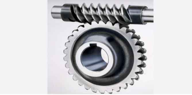
Worm gear reducers consist of a worm (a screw-like gear) and a worm wheel (a helical gear). The unique 90° axis configuration enables high torque multiplication with compact design. Key parameters include:
- Gear Ratio: i=Nworm wheelNwormi=NwormNworm wheel, where NN is the number of teeth.
- Efficiency: η=tanγtan(γ+ϕ)η=tan(γ+ϕ)tanγ, where γγ is the lead angle and ϕϕ is the friction angle.
- Material Pairings: Common combinations include hardened steel worms (e.g., 20CrMnTi, HRC 56–62) paired with bronze worm wheels (e.g., ZCuSn10P1).
2. Common Failures and Root Causes
Worm gear reducers are prone to five primary failure modes. Below is a summary table followed by detailed analysis:
| Failure Type | Root Causes | Critical Parameters |
|---|---|---|
| Wear | Inadequate lubrication, misalignment, abrasive contaminants | Surface hardness (HRC), lubricant viscosity (cSt) |
| Vibration | Imbalanced components, mounting errors, resonance frequencies | Natural frequency fnfn, damping ratio ζζ |
| Oil Leaks | Seal degradation, thermal expansion, improper assembly | Seal material (NBR/FKM), operating temperature |
| Overheating | Excessive friction, overloading, poor heat dissipation | Thermal conductivity kk, ambient temperature |
| Noise | Tooth profile errors, backlash misadjustment, lubrication starvation | Backlash δδ, meshing frequency fmfm |
2.1 Wear in Worm Gear Systems
Wear is the most prevalent issue, often accelerating due to:
- Lubrication Failure: Insufficient oil film thickness (hminhmin) leads to boundary lubrication.hmin=0.5⋅η⋅vE′⋅R0.5hmin=E′⋅R0.50.5⋅η⋅vWhere ηη = dynamic viscosity, vv = sliding velocity, E′E′ = effective modulus, RR = radius.
- Misalignment: Angular or parallel misalignment exceeding 0.1° causes uneven load distribution.
- Material Degradation: Bronze worm wheels (e.g., ZQSn10P1) soften under cyclic loading, reducing hardness from HRC 45 to below 30.
Solution:
- Use high-viscosity synthetic oils (ISO VG 220–320).
- Implement laser alignment tools to ensure <0.05° tolerance.
- Upgrade to hardened worm wheels (e.g., ZA27 alloy, HRC 50–55).
2.2 Vibration and Resonance
Excessive vibration shortens bearing life and disrupts gear meshing. Key contributors include:
- Imbalance: Unbalanced worms generate centrifugal forces Fc=m⋅ω2⋅rFc=m⋅ω2⋅r.
- Resonance: Operating near natural frequencies amplifies vibration amplitudes.fn=12πkmfn=2π1mk
Solution:
- Dynamic balancing to achieve ISO 1940 G2.5 standard.
- Stiffen mounting bases to shift fnfn beyond operating ranges.
2.3 Oil Leakage Mechanisms
Leaks often originate from:
- Seal Failure: Nitrile (NBR) seals degrade above 100°C; switch to fluorocarbon (FKM).
- Thermal Expansion: Coefficient of thermal expansion αα mismatches between housing (steel, α=12×10−6/°Cα=12×10−6/°C) and seals.
Solution:
- Install labyrinth seals or dual-lipped designs.
- Use thermal compensation spacers to mitigate ΔL=α⋅L⋅ΔTΔL=α⋅L⋅ΔT.
2.4 Overheating and Thermal Stress
Thermal failures correlate with power loss PlossPloss:Ploss=μ⋅Fn⋅vPloss=μ⋅Fn⋅v
Where μμ = friction coefficient, FnFn = normal load, vv = sliding velocity.
Solution:
- Optimize cooling fins for heat dissipation Q=h⋅A⋅ΔTQ=h⋅A⋅ΔT.
- Reduce loads to <75% of rated capacity.
2.5 Noise Generation and Mitigation
Gear noise arises from:
- Backlash Errors: Excessive backlash δ>0.1⋅mδ>0.1⋅m (module) causes impact noise.
- Tooth Profile Deviations: ISO 1328 tolerances must be maintained.
Solution:
- Preload adjustments to minimize δδ.
- Precision grinding of worm threads to Ra < 0.8 µm.
3. Case Study: RV Series Worm Gear Reducer
In a recent project, an RV-40 worm gear reducer exhibited severe wear and noise after 8,000 hours. Root cause analysis revealed:
- Lubricant Breakdown: Oil viscosity dropped from 320 cSt to 120 cSt.
- Misalignment: 0.15° angular deviation detected via dial indicator.
Remedial Actions:
- Replaced lubricant with polyalphaolefin (PAO) oil (ISO VG 320).
- Realigned using laser tools (<0.03° residual error).
- Upgraded worm wheel to ZA27 alloy.
Outcome: Operational lifespan extended by 30%, noise reduced by 15 dB(A).
4. Maintenance Protocols for Worm Gear Reducers
Proactive maintenance is critical. Key steps include:
| Activity | Frequency | Tools/Parameters |
|---|---|---|
| Lubricant Analysis | Quarterly | Viscosity, TBN, particle count (ISO 4406) |
| Vibration Monitoring | Monthly | Accelerometers, FFT analyzers |
| Backlash Measurement | Biannually | Dial gauges, ISO 21771 standards |
| Thermal Imaging | Annually | IR cameras (detect hotspots >85°C) |
5. Advanced Modeling and Simulation
Finite Element Analysis (FEA) and computational fluid dynamics (CFD) optimize worm gear performance:
- Stress Distribution:σmax=FnA+M⋅cIσmax=AFn+IM⋅c
- Thermal Profiles: CFD predicts temperature gradients to redesign cooling channels.
6. Conclusion
Worm gear reducers are indispensable yet vulnerable to wear, vibration, leaks, heat, and noise. Through systematic analysis, material upgrades, and precision maintenance, their reliability and efficiency can be significantly enhanced. Future advancements in IoT-enabled condition monitoring and self-lubricating materials promise to further elevate worm gear performance in industrial applications.