1. Introduction
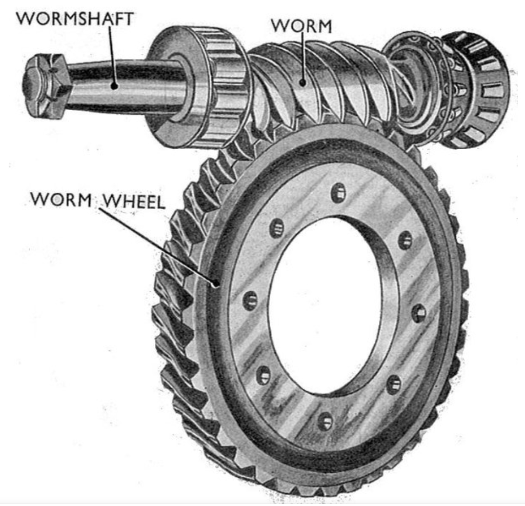
Worm gear transmission systems are widely used in CNC machine tools, automotive industries, and precision instruments due to their advantages of high transmission ratio, smooth operation, low noise, and self-locking capabilities. However, under poor working conditions, severe friction and wear on worm gear tooth surfaces can degrade transmission accuracy. For precision worm gear mechanisms, stringent quality control of tooth pitch is essential. Traditional contact and non-contact measurement methods often suffer from low efficiency, high costs, and limitations in real-world applications. To address these challenges, this study proposes a high-efficiency worm gear tooth pitch detection system based on synchronous displacement sampling principles. The system integrates FPGA-based hardware logic, USB2.0 communication, and C#-developed software to achieve continuous, accurate, and efficient measurements.

2. Theoretical Framework
2.1 Synchronous Displacement Sampling Principle
The core idea involves sampling the angular displacement of the worm gear relative to a reference worm shaft. The transmission error (TE) is defined as the difference between the theoretical and actual angular positions of the output gear:TE=φ0−φ˙0TE=φ0−φ˙0
where φ0φ0 is the theoretical output angle and φ˙0φ˙0 is the measured output angle. For a worm gear pair with a fixed transmission ratio i=Z2Z1i=Z1Z2 (where Z1Z1 and Z2Z2 are the numbers of worm threads and gear teeth, respectively), the nominal tooth pitch PP is derived as:P=π⋅mP=π⋅m
where mm is the module of the worm gear.
2.2 Pulse Subdivision Counting Method
To enhance resolution, a high-frequency clock interpolates fractional pulses between integer counts from optical encoders. The total displacement per sampling cycle is expressed as:Δφ=(Ni+Tc(i)NH(i)−Tc(i−1)NH(i−1))⋅N1Δφ=(Ni+NH(i)Tc(i)−NH(i−1)Tc(i−1))⋅N1
Here, NiNi is the integer pulse count, Tc(i)Tc(i) and Tc(i−1)Tc(i−1) are fractional pulse counts, and NHNH represents the interpolation clock cycles.
3. System Design
3.1 Hardware Architecture
The system comprises three modules:
- Signal Conditioning Circuit: Converts encoder sine/cosine signals to FPGA-compatible square waves.
- FPGA-Based Data Acquisition: Implements pulse counting, interpolation, and USB communication logic using Verilog.
- USB2.0 Communication: Transfers data to a PC via the CY7C68013A chip in slave FIFO mode.
Key Components:
- Optical Encoders: Heidenhain ERN180 (2,048 lines) and RCN8581 (32,768 lines).
- FPGA: Altera Cyclone IV (EP4CE15F23I7) for real-time processing.
- Signal Conditioning: LM311 comparators and TLP521 optocouplers for noise isolation.
3.2 Software Platform
A C#-developed上位机 (host software) provides real-time data visualization, storage, and analysis. Features include:
- Dynamic waveform plotting using TecChart.
- Multi-threaded data acquisition to prevent UI freezing.
- Error analysis algorithms for tooth pitch deviation.
4. Experiments and Results
4.1 Simulation Tests
A simulated encoder signal generator validated the FPGA logic. Parameters included:
- Worm shaft encoder: 2,000 lines, 120 RPM.
- Worm gear encoder: 20,000 lines, 1.2 RPM.
Results:
- Theoretical tooth pitch: P=π⋅3.8=11.938 mmP=π⋅3.8=11.938 mm.
- Measured pitch deviation: <0.02 μm<0.02 μm at 1 MHz interpolation.
4.2 Comparative Experiments
A semi-automatic pitch measuring instrument (Chengdu Surui) served as the benchmark. Tests on a 144-tooth worm gear (m=3.8 mmm=3.8 mm) showed:
| Measurement Aspect | Semi-Automatic Instrument | Proposed System | Error |
|---|---|---|---|
| Left Flank Max Pitch (mm) | 11.9346 | 11.9333 | 1.3 μm |
| Right Flank Min Pitch (mm) | 11.9293 | 11.9300 | 0.7 μm |
| Efficiency (per cycle) | 5 minutes | 2 minutes | 60% ↑ |
5. Error Analysis
The primary error sources include:
- Encoder Nonlinearity: Calibration reduced systemic errors to <0.0142 μm<0.0142 μm.
- Signal Noise: Optocouplers and filtering circuits suppressed EMI.
- Installation Eccentricity: Alignment with dial indicators minimized mechanical deviations.
The system achieved a repeatability of <3.0 μm<3.0 μm, within the 5.0 μm tolerance of industrial standards.
6. Conclusion and Future Work
This study successfully developed a worm gear tooth pitch detection system that combines synchronous displacement sampling, FPGA processing, and high-speed USB communication. Key contributions include:
- A pulse subdivision algorithm enhancing resolution to 0.02 μm.
- Modular hardware design for adaptability.
- 60% faster measurements compared to traditional methods.
Limitations and Future Directions:
- Strong EMI Interference: Shielding and PCB integration will improve robustness.
- Standard Worm Dependency: Error compensation algorithms for non-ideal worms are under development.
- FPGA Optimization: Resource utilization can be enhanced for cost reduction.
This system holds significant potential for industrial applications, particularly in precision manufacturing and quality control of worm gear transmissions.
Keywords: worm gear, synchronous displacement sampling, tooth pitch detection, FPGA, pulse counting.
Tables and Formulas
Table 1: Comparison of Measurement Instruments
| Device Name | Measurement Method | Efficiency | Characteristics |
|---|---|---|---|
| Czech Gear Spect DO-2 | Contact | High | ±0.1 μm precision, modular compatibility |
| Klingelnberg P125 | Contact | High | 4-axis CNC, ±0.05 μm accuracy |
| Semi-Automatic Tool | Contact | Low | 5-minute cycle, manual intervention |
Formula Summary
- Transmission Error:
TE=φ0−φ˙0TE=φ0−φ˙0
- Nominal Tooth Pitch:
P=π⋅mP=π⋅m
- Total Displacement per Cycle:
Δφ=(Ni+Tc(i)NH(i)−Tc(i−1)NH(i−1))⋅N1Δφ=(Ni+NH(i)Tc(i)−NH(i−1)Tc(i−1))⋅N1
