
In the actual measurement of logarithmic spiral bevel gear, there is an offset in the measurement error. This offset can be minimized and can rotate around some deviations related to the gear shaft. The rotation angle is determined as the circumferential pitch error of logarithmic spiral bevel gear. Generally, the pitch error is represented by angle. After the deviation is minimized, the difference between the measurement deviation and the minimum deviation is described as zero order error [61]. According to the definition, the parameters of pitch error can be extracted from the measurement error data of logarithmic spiral bevel gear. Among them, δ 21n ω Is the new error at point I along the normal direction of the tooth surface, and the minimum value of the angle is the value that makes the above function obtain the minimum value θ Value, that is, the parameter value of zero order error. because θ Very small, δ 21n ω It can be expressed as the vertical projection after the rotation of the normal vector Ni on node i, that is:
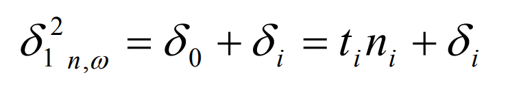
Where:
δ I is the original measurement error of the tooth surface of logarithmic spiral bevel gear at grid node i;
Ni is the normal vector of the tooth surface of logarithmic spiral bevel gear at grid node i;
Ti is the rotation direction vector of the logarithmic spiral bevel gear around the rotation axis at the grid node i;
The formula of rotation direction vector ti is:
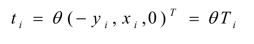
θ Min is the angular error of logarithmic spiral bevel gear.