
I performed a detailed failure analysis on cracked drive bevel pinion gears manufactured from 22CrMoH steel. These pinion gears had already completed the full production sequence, including forging, normalizing, machining, carburizing, quenching, cleaning, low-temperature tempering, and straightening. The longitudinal cracks were found either during final packaging or during assembly. Because such pinion gears are used in medium and large automotive drivetrains and are expected to carry high contact and bending loads with smooth motion, low vibration, and low noise, a crack in a finished pinion gear is a serious quality and reliability concern. I therefore examined the chemical composition, macroscopic appearance, fracture surface, microstructure, grain size, crack path, and scanning electron microscope features of the failed pinion gears to determine the origin and mechanism of cracking.
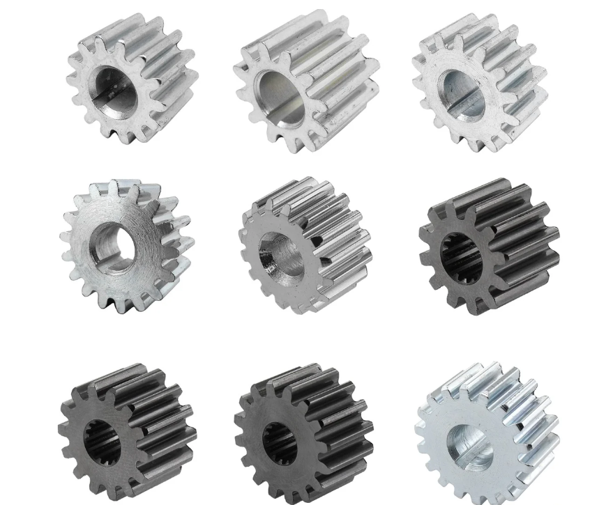
The manufacturing route used for the pinion gears is important because each thermal and mechanical step can contribute to the final residual stress state. I reviewed the process parameters and organized them in Table 1. The pinion gears were cut from bar stock, heated for forging at approximately 1200 °C with a tolerance of ±20 °C, normalized at about 940 °C, machined to shape, carburized and quenched at 920 °C to 930 °C with a carbon potential of 1.1 to 1.2, quenched in an accelerated quench oil at approximately 60 °C, cleaned at 70 °C to 100 °C, tempered at 180 °C to 200 °C, and then straightened. This combination of carburizing, quenching, low-temperature tempering, and straightening creates a complex distribution of hardness, phase transformation strain, thermal strain, and residual stress in the pinion gears. The transition region between the carburized case and the base matrix is particularly sensitive because the carbon content, hardness, microstructure, and volume change vary sharply across that zone.
| Process Step | Parameter Used for the Pinion Gears | Potential Effect on Cracking |
|---|---|---|
| Sawing and blanking | Bar stock cut to length | Initial dimensional control; no direct crack source observed |
| Forging | 1200 ± 20 °C | May influence grain size, banding, and forging flow lines |
| Normalizing | 940 °C | Refines and homogenizes microstructure before machining |
| Machining | Turning, hobbing, spline cutting | Creates V-shaped spline root geometry and notch effect |
| Carburizing and quenching | 920–930 °C; carbon potential 1.1–1.2; accelerated quench oil at 60 °C | Introduces carbon gradient, phase transformation, thermal stress, and quenching stress |
| Cleaning | 70–100 °C | Low thermal impact compared with quenching |
| Low-temperature tempering | 180–200 °C | Relaxes part of the quenching stress but may leave delayed cracking risk |
| Straightening | Mechanical correction after tempering | Can add localized tensile stress, especially near spline roots |
I first verified the chemical composition of the pinion gears because an off-specification heat chemistry can change hardenability, transformation behavior, and susceptibility to quenching cracks. The spectroscopic results are summarized in Table 2. All measured elements were within the specified range for 22CrMoH steel. Carbon was 0.21 wt.%, silicon was 0.30 wt.%, manganese was 0.90 wt.%, chromium was 1.18 wt.%, molybdenum was 0.37 wt.%, phosphorus was 0.011 wt.%, sulfur was 0.005 wt.%, and aluminum was 0.023 wt.%. The low phosphorus and sulfur levels indicated that the steel cleanliness was acceptable, and the measured chromium and molybdenum contents were consistent with the intended high hardenability of the material. I did not find a chemical composition abnormality that could by itself explain the cracking of the pinion gears.
| Element | Specified Range, wt.% | Measured Value, wt.% | Assessment |
|---|---|---|---|
| C | 0.19–0.25 | 0.21 | Conforming |
| Si | 0.17–0.37 | 0.30 | Conforming |
| Mn | 0.60–1.00 | 0.90 | Conforming |
| Cr | 0.90–1.25 | 1.18 | Conforming |
| Mo | 0.35–0.45 | 0.37 | Conforming |
| P | ≤0.015 | 0.011 | Conforming |
| S | ≤0.025 | 0.005 | Conforming |
| Al | ≤0.03 | 0.023 | Conforming |
For a carburized and quenched steel such as 22CrMoH, the carbon profile and the resulting hardenability gradient can be described in a simplified way by diffusion equations. I used the following relation to represent the carbon concentration as a function of depth and time during carburizing:
$$ C(x,t)=C_s-\left(C_s-C_0\right)\operatorname{erf}\left(\frac{x}{2\sqrt{Dt}}\right) $$
where \(C(x,t)\) is the carbon concentration at depth \(x\) and time \(t\), \(C_s\) is the surface carbon potential, \(C_0\) is the initial carbon content, and \(D\) is the diffusion coefficient. The diffusion coefficient depends strongly on temperature according to
$$ D=D_0\exp\left(-\frac{Q}{RT}\right) $$
where \(D_0\) is a pre-exponential factor, \(Q\) is the activation energy for carbon diffusion, \(R\) is the universal gas constant, and \(T\) is the absolute temperature. This relationship explains why the carburizing temperature and time must be controlled closely. In the pinion gears, the carbon potential of 1.1 to 1.2 and the temperature of 920 °C to 930 °C produced a case with a hard, high-carbon surface and a softer, low-carbon core. The transition between the case and the core is not a simple boundary; it is a graded region in which hardness, carbon content, thermal expansion, transformation strain, and yield strength all change with depth.
The hardness profile after carburizing and quenching can be approximated as a sigmoidal function of depth:
$$ H_v(x)=H_{v,0}+\left(H_{v,s}-H_{v,0}\right)\operatorname{erfc}\left(\frac{x-x_c}{w}\right) $$
where \(H_v(x)\) is the hardness at depth \(x\), \(H_{v,0}\) is the base hardness, \(H_{v,s}\) is the surface hardness, \(x_c\) is the effective case depth, and \(w\) is the transition width. A sharper transition produces a steeper hardness gradient, a larger internal constraint, and a greater tendency for stress concentration near the case-core interface. I found that the crack origin in these pinion gears was located at approximately 2 to 3 mm below the surface of the V-shaped spline root, which corresponds to this transition zone.
Macroscopic examination of the failed pinion gears revealed a longitudinal crack on the surface. The visible crack length was approximately 16 cm. The crack appeared relatively straight, and its maximum opening was located at the root of the V-shaped spline, where the separation reached about 0.5 mm. After I sectioned the cracked region, I measured the maximum crack depth to be about 12.6 mm. These observations are summarized in Table 3. The crack did not follow a random path through the component; instead, it was aligned with the longitudinal direction and was clearly associated with the spline root geometry. This geometry acts as a notch and concentrates stress during quenching, tempering, straightening, and subsequent handling.
| Observation | Result | Interpretation |
|---|---|---|
| Crack orientation | Longitudinal | Consistent with longitudinal quenching stress |
| Visible crack length | Approximately 16 cm | Large through-length crack, not a local surface defect |
| Crack straightness | Relatively straight | Suggests stress-driven propagation rather than inclusion-driven wandering |
| Maximum opening | Approximately 0.5 mm at spline root | Highest local tensile stress or weakest constraint at the notch root |
| Maximum depth after sectioning | Approximately 12.6 mm | Deep crack extending from case into core |
| Crack source depth | Approximately 2–3 mm below spline root surface | Located in the case-core transition zone |
The fracture surface provided important evidence about the crack origin and propagation sequence. In the macroscopic fracture examination, I observed that the crack originated below the surface of the spline root, at a depth of about 2 to 3 mm. From that origin, the crack propagated toward both sides and formed a chevron or herringbone pattern. The apex of the chevron pattern pointed back to the crack source. This is a classic indication that the crack initiated at a subsurface point and then spread outward and along the length of the pinion gears. I did not observe macroscopic nonmetallic inclusions at the crack source or on the fracture surface. This observation reduced the likelihood that the cracking was caused by a large inclusion stringer or an obvious casting or forging defect.
I then performed high-magnification metallographic analysis of the crack vicinity and the central matrix. The microstructure near the crack and in the center of the pinion gears was quenched and low-temperature tempered. The grain size was approximately 6.5. These results are summarized in Table 4. The uniformity of the grain size did not indicate severe overheating or abnormal grain growth. The crack itself showed several distinctive features. Below approximately 2 mm beneath the surface, the crack opening became noticeably wider. In contrast, the crack tail and the crack tip had smaller openings. This indicates that the crack opened preferentially within or just below the carburized case, and then extended both toward the surface and into the interior. The crack path was vertical in orientation, serrated in shape, and predominantly intergranular, with occasional branching. The crack tip was sharp, which is characteristic of stress-driven cracking rather than a ductile tearing process.
| Feature | Observation in the Pinion Gears | Significance |
|---|---|---|
| Microstructure near crack | Quenched and low-temperature tempered | Typical of carburized and quenched gear steel |
| Microstructure at center | Quenched and low-temperature tempered | No evidence of abnormal base microstructure |
| Grain size | Approximately 6.5 | No severe overheating indication |
| Crack opening versus depth | Wider below about 2 mm; smaller at tail and tip | Crack initiated below the case rather than at the outer surface |
| Crack path | Serrated, intergranular, occasional branching | Consistent with stress corrosion-like or quenching stress cracking morphology |
| Crack tip | Sharp | Supports brittle stress-driven propagation |
| Oxidation or decarburization | Not obvious along crack flanks | Crack formed after the high-temperature heat treatment stage |
| Nonmetallic inclusions | Not found along crack or nearby | Inclusion-induced cracking is unlikely |
The absence of oxidation or decarburization along the crack flanks was especially important. If the crack had formed at high temperature, for example during forging or during the carburizing soak, the crack surfaces would have been exposed to the furnace atmosphere and would likely show oxidation or abnormal carbon variation. I did not observe obvious oxidation, decarburization, or carburization along the crack. I also did not find nonmetallic inclusions or other metallurgical defects in the crack and its vicinity. Therefore, I concluded that the crack formed after the high-temperature treatment, most likely during or after quenching and possibly after tempering. The morphology and location are consistent with a quenching crack in the pinion gears.
I also examined the crack origin using scanning electron microscopy. The crack source was located approximately 2 to 3 mm beneath the surface. The fracture surface near the source was relatively flat and exhibited cleavage fracture characteristics. The crack propagated in a radiating pattern from the source, and the source and nearby fracture surface did not contain nonmetallic inclusions or other obvious defects. These scanning electron microscopy observations are summarized in Table 5. The flat cleavage facets, radiating pattern, and sharp crack tip all support a brittle, stress-controlled failure mode. The absence of inclusion clusters and porosity further supports the conclusion that the cracking was not caused by a metallurgical discontinuity in the steel, but rather by the thermo-mechanical stress state introduced during processing of the pinion gears.
| Scanning Electron Microscopy Feature | Observation | Interpretation |
|---|---|---|
| Crack source depth | Approximately 2–3 mm below surface | Subsurface initiation in case-core transition |
| Fracture surface near source | Relatively flat | Brittle crack initiation |
| Fracture mode | Cleavage characteristics | Low-temperature or stress-driven fracture |
| Propagation pattern | Radiating from source | Point source with stress-driven expansion |
| Inclusions at source | None observed | Inclusion-initiated fracture unlikely |
To explain the cracking mechanism, I considered the stress history of the pinion gears during carburizing, quenching, tempering, and straightening. During quenching, the surface cools faster than the core. The thermal contraction of the surface is initially constrained by the hotter core, producing thermal stress. At the same time, the surface transforms from austenite to martensite at a lower temperature, while the core transforms later or not at all, depending on hardenability and section size. Because martensite has a larger specific volume than austenite, the transformation produces a volume expansion. The interaction between thermal contraction and transformation expansion creates a complex residual stress field. In a carburized pinion gear, the high-carbon case transforms first and expands, placing the case in compression and the underlying transition zone in tension. The transition zone is therefore a likely location for crack initiation under unfavorable quenching conditions.
The thermal strain can be expressed as
$$ \varepsilon_{th}=\alpha \left(T-T_0\right) $$
where \(\alpha\) is the coefficient of thermal expansion and \(T-T_0\) is the temperature change. The corresponding thermal stress under constrained conditions can be approximated as
$$ \sigma_{th}=\frac{E\alpha \Delta T}{1-\nu} $$
where \(E\) is Young’s modulus, \(\nu\) is Poisson’s ratio, and \(\Delta T\) is the temperature difference between the surface and the interior. The transformation strain depends on the fraction of austenite that transforms to martensite:
$$ \varepsilon_{tr}=\beta f_\gamma $$
where \(\beta\) is the transformation strain coefficient and \(f_\gamma\) is the transformed fraction. The total residual stress can be considered as a superposition:
$$ \sigma_{res}=\sigma_{th}+\sigma_{tr}+\sigma_{mech} $$
where \(\sigma_{mech}\) represents mechanical stresses introduced by machining, straightening, or assembly. In the pinion gears, the V-shaped spline root introduces an additional stress concentration. The notch stress concentration factor can be approximated by
$$ K_t=1+\frac{2a}{\rho} $$
where \(a\) is a characteristic notch depth and \(\rho\) is the notch root radius. A small root radius, which is common in spline roots, increases \(K_t\) and raises the local stress. If the local tensile stress in the case-core transition zone exceeds the local fracture strength, a crack can initiate. Once initiated, the crack grows when the stress intensity factor exceeds the material’s fracture toughness:
$$ K_I=Y\sigma\sqrt{\pi a} $$
and
$$ K_I \ge K_{IC} $$
where \(K_I\) is the mode I stress intensity factor, \(Y\) is a geometry factor, \(\sigma\) is the applied or residual stress, \(a\) is the crack length, and \(K_{IC}\) is the fracture toughness. The elastic strain energy release rate can be written as
$$ G=\frac{K_I^2\left(1-\nu^2\right)}{E} $$
These relationships help explain why a sharp, deep longitudinal crack can develop from a subsurface origin and then extend toward the surface and along the length of the pinion gears. The crack does not need a large inclusion to start; a sufficiently high local tensile stress combined with a sharp notch and a brittle microstructure can provide the necessary driving force.
Delayed cracking after quenching and tempering is also consistent with the observed timing. The cracks were found after the pinion gears had completed final processing and were in packaging or assembly. This means that the crack may have initiated during quenching but only propagated to the visible surface later, or it may have initiated after tempering under the influence of retained residual stress and hydrogen. I considered the possibility of delayed quench cracking, also known as placement cracking or delayed cracking. In such cases, the crack forms after a period of time following quenching, often because residual stresses continue to redistribute, retained austenite transforms slowly, or hydrogen diffuses and accumulates in high-stress regions. The absence of oxidation and decarburization along the crack surfaces supports the conclusion that the crack formed after the high-temperature stage and became visible at a later time. The low-temperature tempering treatment at 180 °C to 200 °C may not have been sufficient to fully relieve the residual stress in the case-core transition zone of the pinion gears.
The tempering stress relaxation can be approximated as
$$ \sigma(t)=\sigma_0\exp\left(-\frac{t}{\tau}\right) $$
where \(\sigma(t)\) is the stress after tempering time \(t\), \(\sigma_0\) is the initial stress, and \(\tau\) is a relaxation time constant. The relaxation time depends on temperature according to an Arrhenius-type relationship:
$$ \tau=\tau_0\exp\left(\frac{Q}{RT}\right) $$
If the tempering temperature is too low or the tempering time is too short, the relaxation time remains long, and a significant portion of the quenching stress remains in the pinion gears. Increasing the tempering temperature and extending the tempering time can reduce the residual stress and lower the risk of delayed cracking. However, tempering must be balanced against the required surface hardness and wear resistance of the pinion gears.
I also considered the role of the quench oil concentration and cooling rate. A faster cooling rate increases the thermal gradient and the amount of transformation strain, but it also improves hardenability and case hardness. A slower cooling rate reduces the thermal gradient and the risk of quenching cracks, but it may reduce hardness if the cooling rate falls below the critical cooling rate. The critical cooling rate depends on the steel composition and the hardenability of 22CrMoH. I expressed this balance conceptually as
$$ \dot{T}_{crit} \le \dot{T}_{actual} \le \dot{T}_{crack} $$
where \(\dot{T}_{crit}\) is the minimum cooling rate required to achieve the desired hardness, \(\dot{T}_{actual}\) is the actual cooling rate, and \(\dot{T}_{crack}\) is the cooling rate above which cracking risk becomes unacceptable. The goal is to keep the actual cooling rate above the critical value but below the cracking threshold. Increasing the quench liquid concentration can reduce the cooling rate while still maintaining sufficient hardenability, especially in the case and transition zone of the pinion gears.
The V-shaped spline root is another critical factor. It is a geometric discontinuity that raises the local stress during quenching and straightening. The notch effect is more severe when the root radius is small, the surface finish is poor, or machining marks remain. The crack origin at 2 to 3 mm below the spline root surface indicates that the highest stress was not at the immediate surface but slightly beneath it, where the case-core transition and the notch stress field interacted. This is a common location for quenching cracks in carburized pinion gears. Once the crack initiated, the longitudinal stress field caused it to extend along the axis of the pinion gears, producing the long, relatively straight crack that I observed.
I summarized the main stress contributions in Table 6. Thermal stress arises from the temperature gradient during quenching. Transformation stress arises from the volume expansion associated with the austenite-to-martensite transformation. Notch stress arises from the V-shaped spline root geometry. Mechanical stress arises from straightening and handling. Residual stress after tempering is the superposition of the unrelaxed portions of these stresses. The case-core transition zone is where the compressive stress in the case and the tensile stress in the core interact, making it the most likely initiation site for the longitudinal quenching crack in the pinion gears.
| Stress Component | Origin | Typical Location | Effect on Cracking |
|---|---|---|---|
| Thermal stress | Temperature gradient during quenching | Surface and near-surface regions | Can create high tensile stress when contraction is constrained |
| Transformation stress | Volume expansion from austenite to martensite | Case, transition zone, and core | Places case in compression and transition zone in tension |
| Notch stress | V-shaped spline root geometry | Spline root and nearby subsurface | Concentrates local stress and lowers crack initiation threshold |
| Mechanical stress | Straightening, fixturing, packaging, assembly | Highly stressed outer fibers and roots | Adds to residual tensile stress and may trigger delayed cracking |
| Residual stress after tempering | Superposition of unrelaxed thermal, transformation, and mechanical stress | Case-core transition and spline root | Provides driving force for crack initiation and propagation |
I further evaluated the process sensitivity of the pinion gears. Several parameters can influence the balance between hardness and cracking risk. The carburizing temperature, carbon potential, quenching temperature, quench oil temperature, quench oil concentration, agitation, tempering temperature, tempering time, and straightening load all matter. In Table 7, I summarize the qualitative sensitivity of the cracking risk to these variables. A higher cooling rate generally increases cracking risk. A higher case carbon content and a sharper case-core transition can increase the transformation stress. A lower tempering temperature or shorter tempering time leaves more residual stress. A larger straightening load adds more mechanical stress. These factors can combine and produce cracking in the pinion gears even when the steel chemistry is fully conforming.
| Process Variable | Change | Effect on Hardness | Effect on Cracking Risk |
|---|---|---|---|
| Quench oil concentration | Increase | May slightly reduce cooling rate and hardness | Decreases cracking risk |
| Quench oil temperature | Increase moderately | Reduces thermal gradient | Decreases cracking risk if hardenability remains sufficient |
| Quench agitation | Increase | Increases cooling rate and hardness uniformity | May increase cracking risk if excessive |
| Carburizing carbon potential | Increase too much | Increases surface carbon and hardness | Increases transformation stress and cracking risk |
| Case depth | Increase excessively | Increases load capacity but also stress gradient | May increase cracking risk at transition |
| Tempering temperature | Increase | May reduce surface hardness slightly | Decreases residual stress and cracking risk |
| Tempering time | Increase | More complete stress relaxation | Decreases delayed cracking risk |
| Spline root radius | Increase | Little direct effect | Reduces notch stress and cracking risk |
| Straightening load | Increase | May improve dimensional accuracy | Increases local tensile stress and cracking risk |
Based on the observations and analysis, I concluded that the cracks in the pinion gears are quenching cracks. The crack origin at approximately 2 to 3 mm below the V-shaped spline root places it in the case-core transition zone, where the stress state changes from compression in the carburized case to tension in the underlying matrix. The V-shaped spline root adds a notch effect, which raises the local stress and promotes longitudinal cracking. The crack morphology is serrated, intergranular in places, occasionally branched, and sharp at the tip, which is consistent with stress-driven brittle fracture. The absence of oxidation, decarburization, and nonmetallic inclusions along the crack indicates that the crack did not originate from a high-temperature defect or an inclusion. The delayed appearance of the crack during packaging or assembly suggests that it may be a delayed quench crack or placement crack, driven by residual stress that was not fully relieved during low-temperature tempering.
The fracture mechanics of the pinion gears can be summarized by the condition for crack initiation and growth. The local stress must exceed a critical value in the transition zone:
$$ \sigma_{local}=K_t\left(\sigma_{res}+\sigma_{mech}\right) $$
The crack initiates when
$$ \sigma_{local} \ge \sigma_c $$
where \(\sigma_c\) is the local fracture strength. After initiation, the crack propagates when
$$ K_I=Y\sigma_{local}\sqrt{\pi a} \ge K_{IC} $$
These equations show that reducing the local stress, reducing the notch factor, increasing the fracture toughness, or reducing the crack size can all lower the cracking risk. In practice, the most effective measures for the pinion gears are to reduce the quenching cooling rate while maintaining hardenability, increase the tempering temperature and time to relieve residual stress, optimize the spline root geometry and surface finish to reduce notch stress, and minimize straightening loads. These measures address the root causes of the quenching crack rather than only detecting the crack after it has formed.
I also examined whether the crack could have been caused by forging or normalizing. The absence of oxidation and decarburization along the crack surfaces makes a high-temperature origin unlikely. The grain size of approximately 6.5 does not indicate severe overheating. The chemical composition is within specification, with low phosphorus and sulfur, and no inclusion clusters were found at the crack source. The microstructure near the crack and in the matrix is normal quenched and low-temperature tempered martensite. These findings all point away from a raw material or forging defect and toward a heat treatment stress problem. The fact that the crack is longitudinal and located at the spline root further supports the quenching crack mechanism, because longitudinal cracks are commonly associated with circumferential or longitudinal residual stresses generated during quenching of cylindrical or gear-like components. The V-shaped spline root acts as a stress raiser, and the case-core transition acts as a mechanical and microstructural discontinuity.
In Table 8, I present the main conclusions from my analysis. The chemical composition conforms to the specification. The crack is longitudinal, approximately 16 cm long, with a maximum opening of about 0.5 mm at the spline root and a maximum depth of about 12.6 mm. The crack source is located approximately 2 to 3 mm below the V-shaped spline root surface. The crack path is serrated and intergranular with occasional branching and a sharp tip. No oxidation, decarburization, or nonmetallic inclusions are associated with the crack. The microstructure is quenched and low-temperature tempered with a grain size of approximately 6.5. The fracture surface near the source is flat and cleavage-like, with a radiating propagation pattern. The crack is therefore a quenching crack, likely a delayed quench crack, that initiated in the case-core transition zone of the pinion gears.
| Conclusion Number | Finding | Interpretation |
|---|---|---|
| 1 | Chemical composition conforms to 22CrMoH requirements | No raw material chemistry abnormality |
| 2 | Longitudinal crack about 16 cm long, maximum opening about 0.5 mm, maximum depth about 12.6 mm | Large stress-driven crack in the pinion gears |
| 3 | Crack source about 2–3 mm below V-shaped spline root surface | Initiation in case-core transition zone |
| 4 | Serrated, intergranular, branched, sharp-tipped crack path | Quenching stress cracking morphology |
| 5 | No oxidation, decarburization, or nonmetallic inclusions along crack | Crack formed after high-temperature processing; inclusion-initiated cracking unlikely |
| 6 | Quenched and low-temperature tempered microstructure; grain size about 6.5 | Normal microstructure, no severe overheating |
| 7 | Flat cleavage-like fracture with radiating pattern | Brittle stress-controlled propagation |
| 8 | Crack found during packaging or assembly | Possible delayed quench cracking or placement cracking |
For corrective action, I recommend that the manufacturer increase the quench liquid concentration to reduce the quenching cooling rate while still maintaining adequate hardenability in the pinion gears. I also recommend increasing the tempering temperature and extending the tempering time to reduce residual stress in the case-core transition zone. The tempering schedule should be validated to ensure that the required surface hardness, case depth, and core properties are still achieved. The spline root geometry should be reviewed to increase the root radius where possible and to improve surface finish, thereby reducing the notch stress concentration. Straightening loads should be minimized, and if straightening is necessary, it should be followed by an appropriate stress relief treatment if the process allows. Quenching agitation and oil temperature should be controlled within a narrow window to avoid excessive thermal gradients. Finally, the pinion gears should be inspected after tempering and before packaging using nondestructive methods such as magnetic particle inspection or ultrasonic inspection to detect any delayed cracks before the pinion gears reach assembly.
I organized the recommended actions in Table 9. These actions target the quenching stress, the tempering stress relief, the notch geometry, and the inspection strategy. Increasing the quench liquid concentration reduces the cooling rate and lowers the thermal gradient. Raising the tempering temperature and time reduces the residual stress and lowers the delayed cracking risk. Optimizing the spline root radius reduces the stress concentration factor. Minimizing straightening loads reduces additional mechanical stress. Improved inspection ensures that any cracked pinion gears are detected before they leave the production line. Together, these measures should reduce the likelihood of longitudinal quenching cracks in 22CrMoH pinion gears.
| Recommended Action | Purpose | Expected Effect |
|---|---|---|
| Increase quench liquid concentration | Reduce quenching cooling rate | Lower thermal gradient and cracking risk |
| Control quench oil temperature and agitation | Maintain stable cooling conditions | Reduce variability in residual stress |
| Increase tempering temperature | Accelerate stress relaxation | Lower residual stress in the pinion gears |
| Extend tempering time | Allow more complete stress relief | Reduce delayed cracking risk |
| Optimize spline root radius | Reduce notch stress concentration | Lower local stress at the crack initiation site |
| Improve surface finish at spline root | Remove machining stress raisers | Reduce crack initiation sites |
| Minimize straightening load | Reduce added mechanical stress | Lower total tensile stress |
| Perform magnetic particle inspection after tempering | Detect surface and near-surface cracks | Prevent cracked pinion gears from reaching assembly |
| Perform ultrasonic inspection where feasible | Detect subsurface cracks | Improve detection of internal quenching cracks |
I also developed a quality control plan for preventing recurrence. The plan is summarized in Table 10. It includes verification of chemical composition, monitoring of carburizing and quenching parameters, validation of tempering, control of straightening, and final nondestructive inspection. The most critical control points are the quench cooling rate, the case-core transition stress, and the spline root geometry. Incoming material should continue to be checked for hardenability and cleanliness, but the current results show that the steel chemistry and cleanliness were acceptable. The failure was therefore primarily a heat treatment and stress management issue rather than a steelmaking issue. For the pinion gears, the combination of high hardenability, carburized case, V-shaped spline root, and low-temperature tempering created a local stress state that exceeded the fracture resistance of the transition zone. By adjusting the quench and tempering processes, the manufacturer can reduce the residual stress and improve the reliability of the pinion gears.
| Control Point | Method | Frequency | Purpose |
|---|---|---|---|
| Chemical composition | Spectroscopic analysis | Per heat | Verify 22CrMoH chemistry |
| Hardenability | End-quench test or equivalent | Per heat or periodic | Confirm hardenability of pinion gears |
| Carburizing atmosphere | Carbon potential monitoring | Continuous | Control case carbon profile |
| Case depth | Microhardness traverse | Per batch or periodic | Verify effective case depth |
| Quench cooling | Oil concentration, temperature, agitation records | Continuous | Control thermal gradient |
| Tempering | Temperature and time records | Per batch | Ensure stress relief |
| Spline root geometry | Dimensional inspection and radius checks | Per setup and periodic | Reduce notch stress |
| Straightening | Load and deflection monitoring | Per part or batch | Minimize added stress |
| Final crack inspection | Magnetic particle or ultrasonic inspection | Per part or batch | Detect quenching cracks in pinion gears |
In summary, I found that the longitudinal cracks in the finished 22CrMoH pinion gears are quenching cracks. The crack origin is located approximately 2 to 3 mm below the V-shaped spline root surface, within the transition zone between the carburized case and the base matrix. This zone experiences a change from compressive stress in the case to tensile stress in the core, and the spline root notch further concentrates the stress. The crack path is serrated, intergranular, occasionally branched, and sharp at the tip, which is characteristic of stress-driven brittle cracking. No oxidation, decarburization, or nonmetallic inclusions were found along the crack, so the crack formed after high-temperature processing and is not related to a raw material or forging defect. The crack was discovered during packaging or assembly, which suggests delayed cracking after quenching and tempering. The most effective preventive measures are to reduce the quenching cooling rate by increasing the quench liquid concentration, increase the tempering temperature and time to relieve residual stress, optimize the spline root radius and surface finish to reduce notch stress, minimize straightening loads, and perform appropriate nondestructive inspection on the finished pinion gears.
These conclusions are consistent with the macroscopic, microscopic, fractographic, and chemical evidence. The pinion gears are made from a high-hardenability carburizing steel, and the combination of a carburized case, a sharp spline root, and a low-temperature tempering treatment created a residual stress state that favored longitudinal cracking. By controlling the quench and tempering processes more precisely, the manufacturer can maintain the required hardness and case depth while reducing the risk of quenching cracks. I recommend that the process changes be validated on a trial batch of pinion gears using the same section size and spline geometry, followed by metallographic examination, hardness testing, residual stress measurement if available, and magnetic particle inspection. This validation will confirm that the modified process reduces the cracking risk without compromising the performance of the pinion gears.