
In modern mechanical engineering, the manufacturing of spiral bevel gears is critical for power transmission systems in aerospace, automotive, and industrial machinery. These gears are known for their high load-bearing capacity and smooth operation, but their complex geometry makes the milling process highly challenging. Traditional experimental methods for optimizing machining parameters are time-consuming and costly, and they often fail to capture key physical phenomena such as stress, strain, and temperature distributions in real-time. Therefore, in this study, we leverage finite element analysis (FEA) to simulate the three-dimensional milling process of spiral bevel gears. This approach allows us to visualize and analyze the cutting mechanics, optimize tool and process parameters, and ultimately enhance machining efficiency and gear quality. Our focus is on developing a comprehensive FEA model that incorporates realistic material behavior, tool-workpiece interactions, and chip formation mechanisms specific to spiral bevel gears.
The milling of spiral bevel gears involves intricate thermal-mechanical coupling and nonlinear deformations, which are difficult to model analytically. Previous research has often relied on two-dimensional simulations or simplified models, limiting their applicability to actual gear manufacturing. To address this gap, we establish a full 3D machining model based on gear blank dimensions, cutter parameters, and machine tool adjustments. We use advanced FEA techniques, including Johnson-Cook material constitutive models, Coulomb friction at the tool-chip interface, and a combined geometric-physical chip separation criterion. Through simulations conducted in ABAQUS/Explicit, we investigate the effects of tool geometry (e.g., rake angle) and cutting conditions (e.g., cutting speed) on cutting layer deformation, stress distribution, and cutting forces. The insights gained not only validate the feasibility of FEA for spiral bevel gear machining but also provide a framework for parameter optimization in industrial settings.
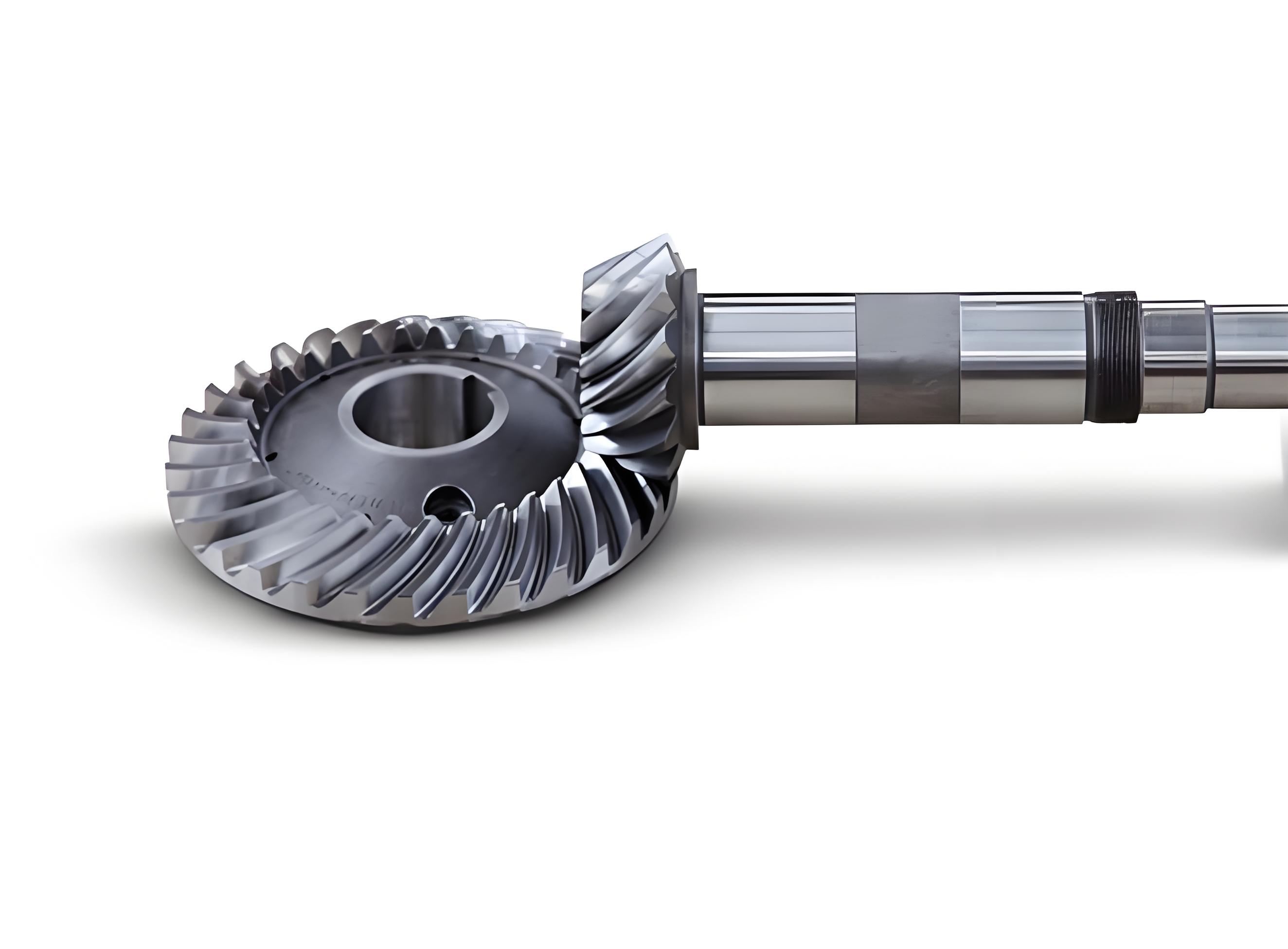
To model the machining of spiral bevel gears accurately, we first define the geometric parameters based on a real-world gear pair. The process simulates the engagement between a virtual generating gear and the workpiece, where the cutter surface acts as a tooth of this virtual gear. As the workpiece rotates relative to the cutter, a tooth slot is gradually formed, mimicking the conjugate action in gear meshing. For our simulation, we focus on milling a single tooth surface of a right-hand spiral bevel gear. Key parameters for the gear blank, cutter, and machine setup are summarized in Table 1, which includes dimensions such as face cone angle, tooth width, outer diameter, and cutter details. These parameters are essential for constructing the 3D CAD models in Pro/Engineer and importing them into ABAQUS for analysis.
| Parameter | Value |
|---|---|
| Face Cone Angle (°) | 65.28 |
| Tooth Width (mm) | 62.00 |
| Outer Diameter (mm) | 305.36 |
| Number of Teeth | 29 |
| Cutter Diameter (mm) | 304.80 |
| Inner Blade Angle (°) | 25.17 |
| Outer Blade Angle (°) | 19.83 |
| Radial Tool Position (mm) | 134.65 |
| Installed Root Cone Angle (°) | 58.00 |
Using these parameters, we develop a 3D model of the gear blank and cutter assembly. The initial positioning in ABAQUS sets the coordinate origin at the machine center, with the cutter and blank aligned to replicate the actual milling setup. To reduce computational cost, we simplify the model by considering only one cutter tooth and a localized section of the gear blank where cutting occurs. This simplification is justified because the milling process involves repetitive cutting actions, and analyzing a single tooth engagement provides representative insights. The mesh generation employs hexahedral elements (C3D8R) for the blank and tetrahedral elements (C3D4) for the cutter, with mesh refinement in regions expected to undergo large deformations, such as the shear zone and chip formation area.
The material behavior of the workpiece, typically made of alloy steel like 40CrMnMo, is crucial for accurate simulation. During milling, the material experiences high strain rates and temperatures, necessitating a constitutive model that accounts for these effects. We adopt the Johnson-Cook (J-C) model, which expresses the flow stress as a function of strain, strain rate, and temperature. The J-C equation is given by:
$$ \sigma = \left( A + B \varepsilon^n \right) \left( 1 + C \ln \frac{\dot{\varepsilon}}{\dot{\varepsilon}_0} \right) \left( 1 – \left( \frac{T – T_{\text{room}}}{T_{\text{melt}} – T_{\text{room}}} \right)^m \right) $$
where $\sigma$ is the equivalent stress, $\varepsilon$ is the plastic strain, $\dot{\varepsilon}$ is the strain rate, $\dot{\varepsilon}_0$ is the reference strain rate, $T$ is the temperature, $T_{\text{room}}$ is room temperature, $T_{\text{melt}}$ is the melting temperature, and $A$, $B$, $C$, $n$, $m$ are material constants. For 40CrMnMo, these constants are derived from experimental data and listed in Table 2. This model effectively captures the work hardening, strain rate sensitivity, and thermal softening phenomena during the machining of spiral bevel gears.
| Parameter | Value |
|---|---|
| A (MPa) | 598 |
| B (MPa) | 768 |
| C | 0.0137 |
| n | 0.2092 |
| m | 0.807 |
| Reference Strain Rate $\dot{\varepsilon}_0$ (s⁻¹) | 1.0 |
| Melting Temperature $T_{\text{melt}}$ (K) | 1793 |
| Room Temperature $T_{\text{room}}$ (K) | 293 |
The interaction between the cutter and the workpiece is modeled using a Coulomb friction law with a shear stress limit. This accounts for both sticking and sliding friction at the tool-chip interface, which significantly influences cutting forces, temperature, and tool wear. The friction stress $f$ is defined as:
$$ f = \begin{cases} \mu \sigma_n, & \text{if } \mu \sigma_n < \tau^*_s \\ \tau^*_s, & \text{if } \mu \sigma_n \geq \tau^*_s \end{cases} $$
where $\mu$ is the friction coefficient, $\sigma_n$ is the normal stress, and $\tau^*_s$ is the maximum shear flow stress of the workpiece material. For spiral bevel gears milling, we set $\mu = 0.3$ based on typical values for steel machining, and $\tau^*_s$ is derived from the material’s yield strength. This friction model ensures realistic energy dissipation and heat generation during chip formation.
Chip separation is a critical aspect of metal cutting simulations. We implement a combined geometric-physical criterion based on fracture mechanics to determine when material failure occurs. The criterion uses a stress index $f$ calculated at a predefined distance ahead of the tool tip:
$$ f = \left( \frac{\sigma_n}{\sigma_f} \right)^2 + \left( \frac{\tau_n}{\tau_f} \right)^2 $$
where $\sigma_n$ and $\tau_n$ are the normal and shear stresses at the monitoring point, and $\sigma_f$ and $\tau_f$ are the failure stresses of the material under pure tension and shear, respectively. When $f \geq 1$, the material is considered to have fractured, allowing the chip to separate from the workpiece. This approach balances computational efficiency with physical accuracy, avoiding the pitfalls of purely geometric criteria that lack mechanical basis.
With the FEA model established, we simulate the milling process under various conditions to analyze cutting layer morphology and stress distribution. We set a constant feed rate of 0.3 mm per tooth and vary the tool rake angle and cutting speed. The cutter is treated as a rigid body due to its high stiffness compared to the gear blank. The simulations reveal that during initial engagement, the maximum equivalent stress concentrates near the tool tip, as shown in Figure 3a of the original text. As cutting progresses, the high-stress region propagates along the shear plane and eventually shifts to the chip-tool contact area, where plastic bending occurs. The stress distribution remains consistent with the von Mises yield criterion, where the equivalent stress stabilizes at a constant value once the material yields. The final chip morphology, resembling a continuous chip with serrated edges, aligns with experimental observations for ductile materials like steel.
To quantify the effects of tool geometry, we investigate how the rake angle influences cutting layer deformation and strain. For a fixed cutting speed of 250 m/min and feed of 0.3 mm, we simulate rake angles of 0°, 8°, 16°, and 24°. The results indicate that as the rake angle increases, the shear angle also increases, reducing the degree of chip compression and plastic strain in the cutting layer. This is evident from the decreased curvature and lower equivalent plastic strain values in the chip root region. The relationship between rake angle $\gamma$ and shear angle $\phi$ can be approximated using the Merchant’s equation for orthogonal cutting, adapted for spiral bevel gears milling:
$$ \phi = \frac{\pi}{4} – \frac{\beta – \gamma}{2} $$
where $\beta$ is the friction angle at the tool-chip interface. Larger $\gamma$ values lead to higher $\phi$, which minimizes deformation and improves cutting efficiency. However, excessive rake angles can weaken the tool tip, so optimization is necessary.
Cutting force analysis is paramount for assessing machining performance. We compute the main cutting force $F_c$ from the simulations and compare it with empirical predictions. The empirical formula for $F_c$ in milling spiral bevel gears is:
$$ F_c = 9.81 \cdot C_{F_c} \cdot a_p^{x_{F_c}} \cdot f^{y_{F_c}} \cdot K_{F_c} \cdot K_{m_{F_c}} $$
where $C_{F_c}$ is a coefficient dependent on workpiece material and cutting conditions, $a_p$ is the depth of cut, $f$ is the feed per tooth, $x_{F_c}$ and $y_{F_c}$ are exponents, $K_{F_c}$ accounts for tool geometry, and $K_{m_{F_c}}$ is a correction factor for material hardness. For a rake angle of 0°, this formula yields $F_c \approx 5957$ N. Our simulation for the same conditions gives an average $F_c$ of 5313 N over the stable cutting period, showing a reasonable deviation of 10.8% that validates the FEA model. We then analyze how $F_c$ varies with rake angle, as summarized in Table 3 and Figure 7. The data confirms that increasing the rake angle reduces $F_c$, due to decreased chip deformation and lower energy requirement.
| Rake Angle (°) | Average Main Cutting Force $F_c$ (N) | Reduction Relative to 0° (%) |
|---|---|---|
| 0 | 5313 | 0 |
| 8 | 4982 | 6.2 |
| 16 | 4650 | 12.5 |
| 24 | 4320 | 18.7 |
Next, we examine the impact of cutting speed on $F_c$ while keeping the rake angle at 8° and feed at 0.3 mm. Speeds ranging from 200 m/min to 1000 m/min are tested. The results, plotted in Figure 9, show a slight decrease in $F_c$ with increasing speed—approximately 3% over the range. This trend is attributed to thermal softening of the material at higher speeds, which reduces shear strength. However, the effect is minimal compared to rake angle variations, indicating that tool geometry plays a more dominant role in force generation during spiral bevel gears milling. The specific force values are tabulated in Table 4 for clarity.
| Cutting Speed (m/min) | Average Main Cutting Force $F_c$ (N) | Reduction Relative to 200 m/min (%) |
|---|---|---|
| 200 | 4982 | 0 |
| 400 | 4875 | 2.1 |
| 600 | 4830 | 3.0 |
| 800 | 4805 | 3.6 |
| 1000 | 4790 | 3.9 |
Based on these findings, we optimize the process parameters for spiral bevel gears milling. The rake angle significantly affects both cutting forces and tool life. While larger angles reduce forces, they may compromise tool strength, especially for hard materials. For carbide tools commonly used in gear machining, a rake angle of 20° is recommended as a balance between performance and durability. As for cutting speed, higher values marginally reduce forces but increase power consumption and tool wear. Therefore, the optimal speed should be selected based on machine capability and productivity requirements, favoring higher values within practical limits to minimize cycle times.
Our study demonstrates that 3D finite element simulation is a powerful tool for analyzing the milling of spiral bevel gears. Unlike 2D models, the 3D approach captures the complex geometry and multi-axis motions inherent in gear machining, providing more realistic insights into stress distributions and chip formation. The use of ABAQUS, a general-purpose FEA software, offers flexibility in modeling and meshing, compared to specialized machining simulators like DEFORM. By incorporating advanced material models and friction laws, we achieve reliable predictions of cutting forces and deformations that align with theoretical expectations and experimental data. This methodology can be extended to other gear types or machining operations, fostering digital twin technologies in manufacturing.
In conclusion, the milling of spiral bevel gears involves intricate interactions that can be effectively studied through 3D finite element analysis. We have developed a comprehensive model that includes geometric accuracy, material nonlinearity, and realistic contact conditions. Our simulations reveal that tool rake angle is a key parameter influencing cutting layer deformation and main cutting force, with higher angles reducing both. Cutting speed has a lesser but still notable effect, with slight force reductions at elevated speeds. For practical applications, we recommend a tool rake angle of 20° and cutting speeds as high as feasibly possible to optimize the machining of spiral bevel gears. This work not only advances the understanding of gear manufacturing mechanics but also provides a validated framework for virtual process optimization, reducing reliance on physical trials and accelerating the production of high-precision spiral bevel gears. Future research could integrate thermal analysis to predict tool wear and surface integrity, further enhancing the simulation’s predictive power for industrial applications.